logo elektroda
logo elektroda
X
logo elektroda

OpenBeken on touch switch with T34 - offline control, 433MHz remotes, cloud

2konrafal1993 324 30
ADVERTISEMENT
Treść została przetłumaczona polish » english Zobacz oryginalną wersję tematu
  • #1 21710459
    2konrafal1993
    Level 38  
    Hello, I have a Chinese touch switch which is based on a t34 processor, its additional functions are 433MHz remote control operation and wifi. Unfortunately it doesn't quite work as I would like because when it is connected to wifi it crashes after a few hours and you can't even operate the touch. I know there is openbeken but I have not found satisfactory answers to some of my questions.

    1) By uploading openbeken can I become completely cloud free and not have to use wifi?
    2. is it then possible to pair two remotes and use the switch by touch only and the 433MHz remotes without having to connect to the cloud. I know I will have to do the setup after wifi but then I don't want any network connection.
    3. is it enough to have a t34 processor to be able to achieve the intended purpose? There are no markings on a few of the ICs and I don't know if this will be a hindrance.
  • ADVERTISEMENT
  • #2 21710531
    p.kaczmarek2
    Moderator Smart Home
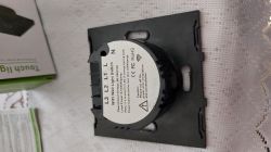
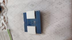
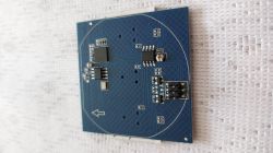
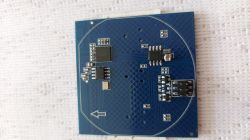
    Hi, I'm happy to help and show the procedure step by step, although the rule of thumb is to show a photo from the middle of the equipment - this will allow you to assess the situation and the operation of the device.

    1. after uploading OBK https://github.com/openshwprojects/OpenBK7231T_App the device works 100% locally, you can then control it with the buttons on the case or optionally via WiFi, but the device itself will not send data to the internet

    2. as long as it is the common type of switch, where the RF chip is connected to the button controller and only it via digital IO to the WIFi module, the RF pairing will continue to work. The remotes will continue to work, etc.
    Refer to this study:
    QTouch WiFi switch plugged into L-wire only - test, interior, schematic .
    Go to paragraph "Pairing with RF433 remote control"

    This is because this type of device has a separate chip that handles the RF and only gives the WiFi module the "button pressed or not" signals, and the WiFi module "doesn't know" if it's "pressing RF" or the user.

    3. we always flash only the WiFi module.


    What you need to do next:
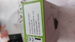
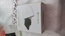
    - first accurate pics of the inside of this device, the packaging too maybe, what model you have exactly
    - then flash reading using https://github.com/openshwprojects/BK7231GUIFlashTool , I will give you more information if needed. Reading a copy of the memory is VERY IMPORTANT, from it you can read the GPIO configurations (otherwise we will guess in GPIODoctor) , in case something goes wrong you can also restore it
    - then programming and configuration
    Helpful post? Buy me a coffee.
  • #3 21710552
    2konrafal1993
    Level 38  
    OpenBeken on touch switch with T34 - offline control, 433MHz remotes, cloud OpenBeken on touch switch with T34 - offline control, 433MHz remotes, cloud OpenBeken on touch switch with T34 - offline control, 433MHz remotes, cloud OpenBeken on touch switch with T34 - offline control, 433MHz remotes, cloud OpenBeken on touch switch with T34 - offline control, 433MHz remotes, cloud OpenBeken on touch switch with T34 - offline control, 433MHz remotes, cloud .
  • ADVERTISEMENT
  • #4 21710571
    p.kaczmarek2
    Moderator Smart Home
    I'm not familiar with this particular board, but that's potentially what I was saying. There is a chance that RF will still work after changing the firmware. Normally I would ask you to investigate the MCU connections to the T34, but.... access to the T34 pads is so poor with a multimeter that I won't bother asking about it.

    Can you read which circuit is the RF? Or both without markings?

    I don't see any programming pads unfortunately. I guess you are facing a procedure like here:
    [BK7231N / T34] Teardown Tuya Generic Wifi Wall Switch 3-fold .

    Worth writing down the model of the device: AY-W602 SH_GANG_2_BL_WF
    Helpful post? Buy me a coffee.
  • #5 21710608
    2konrafal1993
    Level 38  
    p.kaczmarek2 wrote:
    I see no programming pads unfortunately.
    .
    From my inspection it appears that there are not even any RX and TX paths out, this is a handicap but maybe I can sort it out.
    p.kaczmarek2 wrote:
    Can you read which circuit is RF? Or both without markings?
    .
    Both have no markings.
  • #6 21710615
    p.kaczmarek2
    Moderator Smart Home
    If there are no TX and RX paths out , that's a good sign - because that tells us it's not a TuyaMCU based device. So it is a device with what I said mechanism - that is, the RF chip is connected to the button controller and the button controller is connected to the WIFI module.

    I think you have the one here:
    https://www.elektroda.com/rtvforum/viewtopic.php?p=21694094#21694094
    Helpful post? Buy me a coffee.
  • ADVERTISEMENT
  • #7 21710851
    2konrafal1993
    Level 38  
    I have everything connected, I am running to flash but have no idea what to do.
  • #8 21710861
    p.kaczmarek2
    Moderator Smart Home
    Then show a photo of the connections. We will verify. You are to have RX, TX (UART1 port), 3.3V and GND connected. In the flasher you start "Do backup only (read)" or something like that and disconnect the power for a while (3.3V, don't pull the whole USB to UART converter out of the port).

    Or for example have a look here: https://www.youtube.com/watch?v=YQdR7r6lXRY
    The T34 is a BK7231N, so in BK7231N mode.
    Helpful post? Buy me a coffee.
  • ADVERTISEMENT
  • #10 21710904
    p.kaczmarek2
    Moderator Smart Home
    Congratulations, you did it quickly. Will you brag about a photo of how you wired it, or write a few words about how you soldered the T34? A lot of people have problems with this.

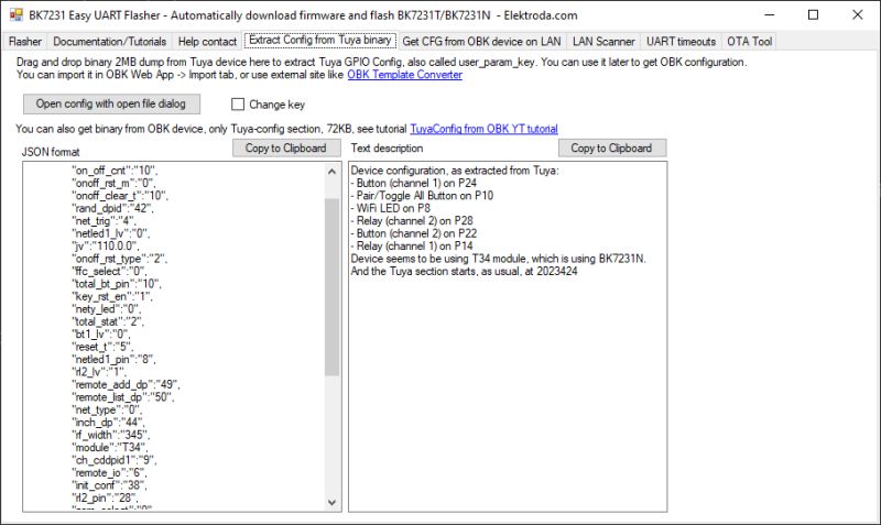
    You already know the GPIO:
    BK7231 Easy UART Flasher window showing extracted Tuya configuration .
    This is the Tuya template:
    Code: JSON
    Log in, to see the code
    .
    Now you can safely upload in OBK, then connect to the OBK AP, on IP 192.168.4.1, pair the device to your WiFi (temporarily, to test) and upload this template:


    .
    Additionally, in the Short Startup Command, add "PowerSave 1" (without the quotation marks) and save. This will save a little power and reduce the heating of the power supply, extending the life of the sprite.

    Provided everything has gone ok, and you haven't hit on some new type of pretty board, the RF should still work, all by itself. At least that's how it's been in the devices we've developed so far. QTouch WiFi switch plugged into L wire only - test, interior, schematic .
    Helpful post? Buy me a coffee.
  • #11 21710930
    2konrafal1993
    Level 38  
    p.kaczmarek2 wrote:
    Congratulations, that went quickly for you. Would you brag about a photo of how you wired it, or write a few words about how you soldered the T34? Lots of people have problems with this.
    .
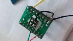
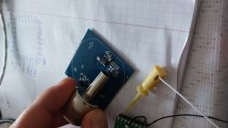
    I soldered with a hotair set at 350°C and used a nozzle of similar size to the chip, poured a generous amount of rma223 gel flux and set the blowing to 4 on a scale of 1-8. Do not over-blow as there are small parts next to it that can be blown off, but too little blowing will make the chip less hot and the soldering process may be prolonged, which is best avoided. The distance between the nozzle and the circuit is a maximum of 5 mm. When heating the circuit do not try to lift it, just slightly move it from side to side and when it floats well then lift it, this method allows you to make sure that all the solders are released and you do not break any tracks.
    Electronic module with wires soldered to a green PCB Hotair nozzle heating an electronic component on a blue PCB over graph paper. .

    I decided to place the circuit in a makeshift stand in order to protect myself in case of a tugging cable that might come off with the solder field.
  • #12 21710933
    p.kaczmarek2
    Moderator Smart Home
    Good method, have to be careful with these pads. It's now uploading the batch. Potentially you could also see if the chip can create a config AP yet without soldering it in place, but I don't know about the coverage. After uploading the batch, you usually just disconnect the power for a while and the AP should appear.
    Helpful post? Buy me a coffee.
  • #13 21710939
    2konrafal1993
    Level 38  
    Please explain what I need to upload and how because at this stage I am already dumbfounded.
  • #14 21710944
    p.kaczmarek2
    Moderator Smart Home
    You select the correct chip in the flasher - you've probably already selected it since you have a copy of the batch - here it's BK7231N / T34. You then have the option "Download firmware from web". This window will download the correct batch itself. Then select it in the list for flashing and click "Write firmware (no backup)" (or something like that). The firmware is loaded, it is "Writing", and it should go through without errors. The batch is uploaded.

    Once you have uploaded the firmware, you can disconnect the power for a while and then restore it, maybe then the Access Point will appear - but I am not sure, because you have soldered out the T34, so I wonder how the range will be.

    Or take 5 minutes and watch the CB2S upload - it's the same BK7231N chip, just in a different casing.


    .
    Helpful post? Buy me a coffee.
  • #15 21711034
    2konrafal1993
    Level 38  
    After soldering the chip I have a wifi connection but it does not open the 127.0.0.1 address.
  • #16 21711050
    p.kaczmarek2
    Moderator Smart Home
    The address 127.0.0.1 is localhost, who gave it to you? Both I gave 192.168.4.1 today , the same in the video from me is this address.
    Helpful post? Buy me a coffee.
  • #17 21711054
    2konrafal1993
    Level 38  
    Sorry, my mistake I was suggesting some video. I managed to get it to work on the address 192.168.4.1 and I don't really know what to rewrite or where.
  • #18 21711063
    p.kaczmarek2
    Moderator Smart Home
    1. pairing with WiFi
    Optionally in Options->Short startup command add a block of text:
    
    PowerSave 1
    startDriver SSDP
    
    .
    to enable power saving and device visibility in "Network" on Windows.
    In Options -> Configure WiFi enter your SSID and network password from 2.4GHz

    2. pin configuration
    Wrap up the new IP of the device, either see in "Network" on Windows how you enabled SSDP, or preferably on the router in DHCP clients.
    Open the Web App, there in Import paste Tuya's JSON from the previous post:
    Here's the timestamp link to where https://youtu.be/VDbaLR_0YWs?t=46
    From this stage the buttons should work, both the physical ones on the device and the ones on the web panel.
    Helpful post? Buy me a coffee.
  • #19 21711079
    2konrafal1993
    Level 38  
    What if I have entered my wifi password incorrectly and have no connection?
  • #20 21711086
    p.kaczmarek2
    Moderator Smart Home
    You need to switch on AP mode. To do this, do a reboot five times, i.e., you unplug the power, wait 1 second (until the capacitors discharge), switch it on again.... and after a second again. And in this way 5 times. Then the OBK will boot into AP mode.
    Helpful post? Buy me a coffee.
  • #21 21711148
    2konrafal1993
    Level 38  
    I have no idea why it doesn't connect with the router, the router is also a deadbeat but it has to be that way for now.
  • #22 21711168
    p.kaczmarek2
    Moderator Smart Home
    In that case, maybe approach it differently. Since you don't ultimately want WiFi, do the whole setup in AP mode. This should work, the only downside is that the Web App is downloaded from Github live, so you need to have a wired internet connection and be connected to the OBK AP at the same time.

    Alternatively, you can manually punch these pins in Configure Module instead of importing JSON.

    Router obviously 2.4 GHz?
    Helpful post? Buy me a coffee.
  • #23 21711172
    2konrafal1993
    Level 38  
    Yes 2.4GHz, I don't use 5GHz because it kept disconnecting my various devices.
    The router model is DN8245X6-10
    The wifi settings are:
    AES encryption
    Authentucation Mode wpa2
    WMM enabled.
    The network name is simply INTERNET.
  • #24 21711780
    p.kaczmarek2
    Moderator Smart Home
    Or perhaps an antenna issue? Are you testing after soldering in place on the PCB?
    Helpful post? Buy me a coffee.
  • #25 21711890
    2konrafal1993
    Level 38  
    The chip itself gives no signal and was not visible even on the laptop next to it, I am doing all the tests on the PCB. I'm doing the whole procedure for the first time so I'm assuming I've made a mistake somewhere, I'm going to check the quality of the solders because sometimes a weaker contact can happen and I'm taking that into account.

    Added after 32 [minutes]: .

    Just to be sure, I checked the MAC address because supposedly it can be removed and it is the same as it was originally. The network from my router is detected by the module and I have -69dB there so the devices see each other. I did a test that the phone is the access point and here it works except that I have a low internet speed from the sim because it is a village but it is possible to log in and do something there. I stand by my opinion that this router is a disaster because it's not the first device that has problems with a router, before I moved I had a TP link for 100zł and there were no such miracles because everything worked. I don't know what to do because everything seems to be fine but it doesn't work.

    The switch connects to the hotspot on the laptop so that something is going on with the router. I still want to pair the remotes because we have two, that would be all I need.

    I have investigated what I could and the pilot rf receiving circuit sends a signal to the T34 on the CEN leg, the RF circuit leads match the WF480RA. I checked with an oscilloscope and the RF pilot signal is received by the circuit and sent to the T34 but that is where my knowledge and ability to succeed ends.
  • #26 21713895
    p.kaczmarek2
    Moderator Smart Home
    CEN is the RESET pin, its shorting to ground resets the WiFi module. It is not likely that RF is received there?
    Helpful post? Buy me a coffee.
  • #27 21714043
    2konrafal1993
    Level 38  
    I just don't understand what's going on either, with an oscilloscope I have examined the signal at the output of the remote control receiver circuit and there is when I press the piot. A series of rectangles is arranged, it resembles a typical digital signal waveform and I have exactly the same thing when I connect the oscilloscope to pin 21 of the CEN, the continuity of the path is also maintained. Maybe the Chinese know an additional function of this pin and used it here, what is interesting is that no reset occurs during transmission of the remote control and on this pin itself the state changes from high to low.
  • #28 21714052
    p.kaczmarek2
    Moderator Smart Home
    Just to be sure - are the relays now no longer responding to the remote control?
    Helpful post? Buy me a coffee.
  • #29 21714059
    2konrafal1993
    Level 38  
    They don't respond, even in the pin doctor I don't see any response.
  • #30 21714063
    p.kaczmarek2
    Moderator Smart Home
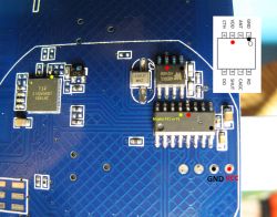
    That must have changed something in the party, because until recently it was like this:
    divadiow wrote:
    .

    Close-up of a PCB with several integrated circuits and a pinout diagram. .
    .

    https://www.elektroda.pl/rtvforum/topic4036975-60.html#21127139

    And the RF worked without the participation of the WiFI module.
    Helpful post? Buy me a coffee.

Topic summary

The discussion addresses a Chinese touch switch based on the T34 (BK7231N) processor featuring 433MHz remote control and WiFi connectivity, which crashes after prolonged WiFi use. Uploading OpenBeken firmware enables fully local operation without cloud dependency, allowing control via touch and 433MHz remotes without network connection after initial WiFi setup. The RF chip is typically connected to the button controller, which interfaces digitally with the WiFi module, preserving remote functionality post-firmware update. The device lacks visible RX/TX programming pads, complicating flashing, but soldering the T34 chip with hot air rework is feasible. Firmware flashing involves selecting BK7231N/T34 in the flasher, downloading the firmware from the web, and writing it to the device. After flashing, the device may create an Access Point at 192.168.4.1 for configuration. WiFi setup requires entering SSID and password in the web app or configuring pins manually via JSON import. If WiFi credentials are incorrect, rebooting the device five times triggers AP mode for recovery. The router used operates on 2.4GHz with AES encryption and WPA2 authentication. The user is advised to perform setup in AP mode if WiFi is unreliable, noting that the web app is downloaded live from GitHub, requiring simultaneous internet and device AP connection.
Summary generated by the language model.
ADVERTISEMENT