logo elektroda
logo elektroda
X
logo elektroda
Dostępna jest polska wersja

Czy wolisz polską wersję strony elektroda?

Nie, dziękuję Przekieruj mnie tam

[BK7231N / T34 ] Teardown Tuya Generic Wifi Wall Light Switch 3 Gang

CameronDev 31710 115

TL;DR

  • A Tuya Generic WiFi Wall Light Switch 3 Gang with a BK7231N/T34 was torn down and prepared for OpenBeken flashing.
  • The front glass lifts off from the bottom opening, and the motherboard unclips easily, but the T34 QFN chip has no exposed programming pads.
  • It shipped from AliExpress with firmware 1.3.10 and was already patched against the CloudCutter exploit.
  • Hot-air desoldering, jumper wires, and bk7231flasher were needed to dump and reflash the chip, and the T34 was resoldered successfully.
  • OpenBeken and ESPHome pin maps are provided, but the dump could not extract Tuya config, so this is a difficult mod to attempt.
Generated by the language model.
ADVERTISEMENT
📢 Listen (AI):
  • Close-up of a small electronic board with thin wires soldered and labeled TX/RX, Ground, and 3.3V.
    Here is how you can flash a T34-based wall switch with OpenBeken. This switch has no programming pads available, so desoldering T34 in QFN case is required.

    Purchased from AliExpress: https://www.aliexpress.com/item/1005005732402318.html

    Packaging of a touch light switch with an illustration of a finger touching the panel. Close-up of a green product packaging with technical parameters of a wall switch.

    Nothing special in the box, comes with a capacitor and some screws, and a wiring diagram.

    Back of a WiFi wall switch with labels L3, L2, L1, L, and N. Touch switch with three buttons on a white panel.

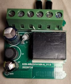
    Teardown is very straightforward, a flat head screwdriver is all that is required: Just gently lever the front glass off (There is an opening at the bottom for this purpose). Removing the motherboard is as simple as unclipping 4 plastic clips and lifting it up. It is joined to the back via 6 pins.

    The image shows a disassembled wall switch with three touch buttons and a circuit board. Two printed circuit boards with electronic components, one placed in a white frame.
    Close-up of a printed circuit board with several electronic components. Close-up of a circuit board with three white rectangles on a blue background.

    Flashing is a lot less straightforward. This switch came patched for the cloudcutter exploit. (Firmware 1.3.10).
    The 4 pads on the board don't appear to be connected to the T34 which is the brains of the operation. The far right pad is 3.3V, the one next to it is GND, unsure of the other two.

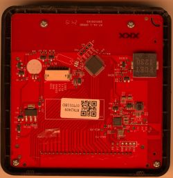
    All the pins of the T34 are hidden, so flashing is non-trivial. I had to hot air desolder it, solder some jumper wires, and then dump/flash it via bk7231flasher. Miraculously, I managed to resolder it successfully. This is not for the faint of heart.
    The dump also failed to extract the tuya config, but I was able to reverse it via inspection.

    Close-up of T34 chip with soldered wires.

    OpenBeken config is:

    
    {
      "vendor": "Tuya",
      "bDetailed": "0",
      "name": "Tuya Generic Touch Light Switch 3 Gang",
      "model": ???",
      "chip": "BK7231N",
      "board": "",
      "flags": "1024",
      "keywords": [
        "T34",
      ],
      "pins": {
        "8": "WifiLED;55",
        "14": "Rel;1",
        "22": "Btn;3",
        "23": "Btn;2",
        "24": "Btn;1",
        "26": "Rel;2",
        "28": "Rel;3"
      },
      "command": "",
      "image": "https://obrazki.elektroda.pl/2902642800_1708303164.jpg",
      "wiki": "https://www.elektroda.com/rtvforum/viewtopic.php?p=20968165"
    }


    ESPHome Config:
    
    esphome:
      name: lightswitch-3gang
    
    # Enable logging
    logger:
    
    # Enable Home Assistant API
    api:
      encryption:
        key: "REPLACEME"
        
    ota:
      password: "REPLACEME"
    
    wifi:
      ssid: !secret wifi_ssid
      password: !secret wifi_password
      fast_connect: true
      reboot_timeout: 0s
    
      # Enable fallback hotspot (captive portal) in case wifi connection fails
      ap:
        password: !secret wifi_password
    captive_portal:
    
    button:
      - platform: restart
        name: "Restart"
    
    sensor:
      - platform: wifi_signal
        name: "WiFi Signal Sensor"
        update_interval: 60s
    
    bk72xx:
      board: generic-bk7231n-qfn32-tuya
    
    binary_sensor:
      - platform: gpio
        id: binary_switch_1
        pin:
          number: P22
          inverted: true
          mode: INPUT_PULLUP
        on_press:
          then:
            - switch.toggle: switch_1
      - platform: gpio
        id: binary_switch_2
        pin:
          number: P23
          inverted: true
          mode: INPUT_PULLUP
        on_press:
          then:
            - switch.toggle: switch_2
      - platform: gpio
        id: binary_switch_3
        pin:
          number: P24
          inverted: true
          mode: INPUT_PULLUP
        on_press:
          then:
            - switch.toggle: switch_3
    
    switch:
      - platform: gpio
        id: switch_1
        name: Relay 1
        pin: P28
      - platform: gpio
        id: switch_2
        name: Relay 2
        pin: P26
      - platform: gpio
        id: switch_3
        name: Relay 3
        pin: P14
    
    status_led:
      pin: 
        number: P8
        inverted: true  # Inverting enables the key backlights.


    Hope this is helpful to someone, but I would strongly advise not purchasing this one. With the T34 package, and no exposed pads or silk screen, these are non-trivial to flash.
    Attachments:
    • readResult_BK7231N_QIO_2024-18-2-14-38-38.zip (1.04 MB) You must be logged in to download this attachment.

    Cool? Ranking DIY
    About Author
    CameronDev
    Level 4  
    Offline 
    CameronDev wrote 12 posts with rating 15, helped 1 times. Been with us since 2024 year.
  • ADVERTISEMENT
  • #2 20968230
    p.kaczmarek2
    Moderator Smart Home
    This is the most pro way of flashing I've ever seen here:
    Image of an electronic circuit with connected wires on a board, labeled: TX/RX, Ground, 3.3V, and CEN bridged to ground.
    Just a quick question - was using CEN really necessary?
    Helpful post? Buy me a coffee.
  • #3 20968315
    CameronDev
    Level 4  
    p.kaczmarek2 wrote:
    This is the most pro way of flashing I've ever seen here:


    A pro wouldn't have taken 3 hours to do it :D

    p.kaczmarek2 wrote:
    Just a quick question - was using CEN really necessary?


    Don't know, I didn't try without grounding CEN. I just read somewhere that I needed to ground it.
    Either way, TX/RX are also inaccessible, so it required removing the IC.
  • #4 20968350
    ferbulous
    Level 18  
    Hi @CameronDev
    How did you apply the solder paste to the back chip?
    Do you cover the entire back or just meticulously apply to each of the small pads?
  • ADVERTISEMENT
  • #5 20968363
    CameronDev
    Level 4  
    ferbulous wrote:
    Hi @CameronDev
    How did you apply the solder paste to the back chip?
    Do you cover the entire back or just meticulously apply to each of the small pads?


    I didn't use solder paste. I tried to add solder to the board using the soldering iron, but it mostly went onto the ground and ignored the pins.
    Those pads are TINY. The wires in that picture are 0.25mm copper wires. The first time I put the chip back on, I didn't do it right. It powered up and connected to WiFi, but only one relay worked. I had to re-flow it while putting more pressure on the IC with some tweezers to get it 100% working.

    I am 100% an amateur, and I think I got very lucky. I suspected someone with more experience/skill would have a much more reliable outcome.
  • #6 20968413
    ferbulous
    Level 18  
    I see, so it’s mostly solder reflow and you heat it up with hot air.
    I tried it once with esp32 ic chip that got displaced when i was desoldering. Didn’t quite work for me though
  • #7 20968437
    divadiow
    Level 38  
    >>20968165

    this is impressive. kudos
  • #8 20975882
    jkwim
    Level 13  
    Just curious to know the temperature ranges and the air flow settings use in Hotair guns that you use for these kind of desoldering/soldering.

    Some recommend preheating the board and then having a quick blast of 400 degrees C for a short period to avoid damages to the surrounding components.
  • #9 20975908
    p.kaczmarek2
    Moderator Smart Home
    It varies from station to station, I have a 50$ station that can't desolder a component at 450C and I have a 400$ station that desolders the same component at 350C.
    Helpful post? Buy me a coffee.
  • #12 20983797
    jkwim
    Level 13  
    CameronDev wrote:
    I didn't pre-heat the board, and used one of these:

    https://www.aliexpress.com/item/1005005855040180.html
    Soldering station 8858 with digital hot air gun and accessories.

    I just set it as hot as it will go, with a fairly narrow nozzle.
    I put kapton tape on the other nearby components, so if they melted, at least they should stay in place.


    :-)
    I have the exact same device. I am a novice when it comes to use of heat gun. So far I have used it once to remove a CB3S module. Some nearby small SMD components flew off the board.

    That is why I wanted to understand the best practice before my next job.

    So what is the temperature that you use? And the air flow setting on this device?
  • #13 20983826
    CameronDev
    Level 4  
    Flux I used: https://www.ebay.com.au/itm/203741564643

    Ill try work out the settings, but i suspect they are on the defaults. The controls for that hot air thing are awful.

    I am also a novice (as demonstrated by the cheap tools), but I think taping down anything you dont want to move is a good idea.
  • #14 20983830
    p.kaczmarek2
    Moderator Smart Home
    jkwim wrote:
    So far I have used it once to remove a CB3S module. Some nearby small SMD components flew off the board.

    Did you use the Pb solder and flux trick?


    jkwim wrote:

    So what is the temperature that you use? And the air flow setting on this device?

    I've did a small research on that and it turned out that the same temperature setting (like 350C) gives different results on various stations:
    https://openshwprojects.github.io/hotair/350c.html
    So, I think you should experiment yourself for the best results.
    Helpful post? Buy me a coffee.
  • ADVERTISEMENT
  • #15 20983845
    divadiow
    Level 38  
    p.kaczmarek2 wrote:
    Did you use the Pb solder and flux trick?


    sorry to chime in on everything it probably seems! I did the pb/flux trick like your video once but it seems if you have a module with 3 sides of soldered pins you can't liquify the pb fast enough between them all. I've not tried a 2-sided module yet though.

    CameronDev wrote:
    The controls for that hot air thing are awful.

    good to know. I was looking at the 8858 too. but I thought maybe something like this instead https://vi.aliexpress.com/item/1005006047499507.html

    maybe theyre all much of a muchness until you bump up your budget to a certain level?
  • #16 20983879
    p.kaczmarek2
    Moderator Smart Home
    divadiow wrote:
    I did the pb/flux trick like your video once but it seems if you have a module with 3 sides of soldered pins you can't liquify the pb fast enough between them all. I

    My video used JCD 8908 at 450C I think. Review:
    https://www.elektroda.pl/rtvforum/topic3970314.html
    (Use Google Translate)
    but as I said, 450 on one station is not like 450 on the other:
    https://openshwprojects.github.io/hotair/350c.html
    https://openshwprojects.github.io/hotair/450c.html

    divadiow wrote:
    I've not tried a 2-sided module yet though.

    Two sided module trick:


    Helpful post? Buy me a coffee.
  • #17 20985028
    CameronDev
    Level 4  
    I used 480c (Whatever that actually ends up being), and the fastest fan speed. Desoldering smaller things is easier, the T34 came off fairly easily.
  • #18 21007112
    t2004dd
    Level 5  
    >>20968230
    Hi ! About bridge from PIN 9 - CEN to the GND : do you have it permanently or short up it when flash was started ? and what baud rate did you use ?
  • ADVERTISEMENT
  • #19 21007722
    t2004dd
    Level 5  
    I flashed T34 chip successfully.
    Bridge CEN is not needed. You can start flashing if you just interrupt 3.3V , attached to the PIN8.
    I flashed it with baud rate 921600.

    BK7231N chip with soldered wires on a white surface.
    Electronic module with green screw terminal block and black relay on a PCB.
  • #20 21007826
    p.kaczmarek2
    Moderator Smart Home
    Good job! I actually never use CEN for flashing these days, but I haven't really encountered any T34s so far, only BK7231N
    Helpful post? Buy me a coffee.
  • #21 21007852
    t2004dd
    Level 5  
    Btw, Smart switch came from the same seller in Orange box. My advice is not to buy such switches, to avoid having the extra trouble of soldering out the T34 chip.
  • #22 21008328
    CameronDev
    Level 4  
    t2004dd wrote:
    My advice is not to buy such switches


    I wonder if this is what actually kills 3rd party firnware for Tuya devices. Im definitely not going to buy T34 devices if this is what is required to flash them. Would be nice if Tuya could provide an official flashing method.
  • #23 21008716
    t2004dd
    Level 5  
    I have bought them from Ali very cheap. 1.87 Euro for one. May be it was reason of big discount :) Today 18.03 they are still in Ali for the same price. If it doesn't bother anyone to do a little reflow.
  • #24 21008885
    ferbulous
    Level 18  
    Does the EU version has the same pcb with t34?
    I’ve already purchased them so it might take another 1-2 weeks to update

    @t2004dd did you put kapton tape around the components next to the T34 chip before desoldering?
  • #25 21009070
    t2004dd
    Level 5  
    Yes, when I was working with the chip, everything around it was taped up with Kapton tape to keep the other parts from blowing away.
    I attached picture with the box and case, came to me with T34. Better look for old stock in white boxes. They came with PADs for TX/RX.

    Two boxes with a Wi-Fi smart switch on a table.
  • #26 21014447
    p.kaczmarek2
    Moderator Smart Home
    I would like to get one such switch for the upcoming video for our Youtube channel . If anyone has one to spare, let me know.

    @t2004dd I don't think that all orange box switches are T34, or at least some time ago I was flashing a batch in orange boxes that weren't T34. My "orange boxes" were bought on Allegro.

    Added after 1 [hours] 27 [minutes]:

    EDIT: @t2004dd see here:
    https://www.elektroda.com/rtvforum/topic3874289-240.html#20546731
    This user has the same (?) device - even Tuya sticker matches - but in CB2S version:
    Two images of a Wi-Fi switch with a CB2S module and an orange box.
    Helpful post? Buy me a coffee.
  • #27 21014957
    CameronDev
    Level 4  
    Where would I need to ship it to? Can you cover shipping? I don't have any real use for mine to be honest. Also, will 240v work for you?

    It might actually be cheaper to just order you one from Aliexpress, I am a bit far away in terms of shipping.
  • #28 21015737
    karayoooo
    Level 1  
    Hello guys

    it can be done directly without unsoldering T34.
    Here in a tuya socket.
    Yes It's tricky and yes a pcb pad is quite (but not) broken but it works !

    Close-up of a circuit board with an integrated circuit and a missing capacitor marked as C1.
  • #29 21016910
    CameronDev
    Level 4  
    @karayoooo Looks like your pads are exposed, so that's helpful. On my switch, they were completely covered. The serial pins were not extended out of the T34 at all. I tried to stick some sharp thin pointy sticks in under the package, but no luck there
  • #30 21021190
    Raufaser
    Level 10  
    Hi. Since you are just talking about soldering a T34: I am looking for a breakout board for the T34. It is a QFN32 with 0.6mm pitch. I can't find one :-/ Strangely there are boards with 0.5mm and 0.65mm pitch. Do you guys have any idea? Maybe woth trying the 0.65mm one?
📢 Listen (AI):

Topic summary

✨ The discussion focuses on the teardown and flashing process of Tuya generic WiFi wall light switches based on the BK7231N chip and T34 board, particularly 3-gang and 2-gang variants. The T34 chip is in a QFN package with no accessible programming pads, requiring desoldering for flashing with OpenBeken firmware. Users share detailed methods for desoldering and resoldering the T34 chip using hot air guns (temperatures around 350-480°C), flux, and soldering techniques, emphasizing the difficulty due to tiny pads and risk of PCB damage. Alternatives like needle probes for direct serial connection are discussed but often limited by concealed pads. Flashing is done via UART or SPI using FTDI232RL or CH340G-based USB-TTL adapters, with baud rates up to 921600. Some users report success without grounding the CEN pin by interrupting 3.3V supply to enter flash mode. Firmware extraction challenges include missing or manually created JSON configs. The devices often include additional components like BL0937 power measurement chips and WF480RA RF transceivers for remote control, sometimes unadvertised. Community members provide pin mappings for relays, buttons, and LEDs, and share templates for OpenBeken configuration. PowerSave mode and local NTP server support in OpenBeken are also mentioned. The discussion includes warnings about the complexity of flashing T34 devices, recommending caution and skill in SMD rework. Some users note differences in PCB versions, with older white-box versions having accessible TX/RX pads. Overall, the thread serves as a comprehensive resource for hardware hacking and firmware replacement on T34-based Tuya switches.
Generated by the language model.

FAQ

TL;DR: 480 °C hot-air, 921 600 bps UART and a steady hand let users flash Tuya T34 wall switches; “This is the most pro way of flashing I’ve ever seen” [Elektroda, p.kaczmarek2, post #20968230] Success rate rises to 100 % once VCC is power-cycled during upload [Elektroda, t2004dd, post #21007722]

Why it matters: The right method turns a €1.87 cloud-locked switch into fully local Home-Assistant hardware.

Quick Facts

• Chipset: BK7231N / T34, QFN32, 0.6 mm pitch [Elektroda, CameronDev, post #20968165] • Stock firmware: Tuya 1.3.10 (Cloudcutter-patched) [Elektroda, CameronDev, post #20968165] • Reliable upload speed: 921 600 bps HID-Download or BK7231GUI [Elektroda, t2004dd, post #21007722] • Reflow window: 400–480 °C, <60 s with narrow nozzle [Elektroda, CameronDev, post #20985028] • Typical cost: €1.87 per switch on AliExpress [Elektroda, t2004dd, post #21008716]

What makes the T34 wall switch harder to flash than older Tuya models?

All UART pins are hidden under the QFN-package and the four test pads carry only 3 V3 and ground; TX/RX are not routed out, so access requires chip removal or micro-probes [Elektroda, CameronDev, post #20968165]

Do I have to ground the CEN pin to enter boot mode?

No. Multiple users flashed successfully by simply interrupting 3 V3 on pin 8; CEN left floating works [Elektroda, t2004dd, post #21007722]

Which pads are safe for power connection?

On the 3-gang PCB the far-right pad is 3 V3 and the next one is GND [Elektroda, CameronDev, post #20968165] Measure before soldering because board revs vary.

What baud rate and software give the best results?

921 600 bps with BK7231GUIFlashTool or hid_download_py completes in ≈10 s [Elektroda, t2004dd, post #21007722] Lower rates work but increase timeout risk.

Can I flash without desoldering the T34?

Yes. Two dress-maker needles pressed against pins P10/P11 (RX/TX) plus soldered VCC/GND let users dump and write firmware without lifting the IC [Elektroda, divadiow, post #21117908]

Recommended hot-air settings for full removal?

Pre-heat optional; 400 °C melts the solder in ≈40 s, 480 °C in ≈25 s. Shield neighbouring parts with Kapton to stop them “flying off” [Elektroda, CameronDev, #20985028; jkwim, #20983797].

I get “Failed to extract Tuya keys – no json start found”. What now?

The key block is often absent on brand-new units; open the binary in a hex editor or copy a community template and edit pins manually [Elektroda, CameronDev, post #21032342]

Does the switch still accept RF remotes after conversion?

Yes. The WF480RA transceiver and its MCU remain untouched; pairing is done by holding the touch button, then pressing the RF remote key [Elektroda, p.kaczmarek2, post #21127139]

How can I lower idle temperature and power draw?

Enable PowerSave with “powersave 1”; users saw PCB temperature drop >10 °C and no automation issues [Elektroda, kalikum, post #21486484]

Is there a JTAG method for this MCU?

No documented JTAG routine exists for BK7231N/T34; only UART (PIO8 boot strap) and SPI NOR reflashing are supported officially [Elektroda, p.kaczmarek2, post #21050745]

Where can I find ready OpenBeken or ESPHome configs?

Templates for 1-, 2- and 3-gang variants are posted in the thread; import JSON starting with vendor “Tuya” and adjust pin list (e.g., P14/P26/P28 for relays) [Elektroda, johnypean, post #21111773]

Can I add a temperature sensor inside the switch?

Yes. DHT11 works on any free GPIO; run startDriver DHT11 Pxx. DS18B20 is not yet merged into OpenBeken codebase [Elektroda, p.kaczmarek2, post #21060852]

3-Step: Needle-flash without desoldering

  1. Solder thin wires to 3 V3 and GND test pads. 2. Hold two sewing needles on pins P10 (RX) and P11 (TX); tape them in place. 3. Power-cycle 3 V3, click “Upload” in BK7231GUI, release after “Sync OK”.[Elektroda, divadiow, post #21117908]
Generated by the language model.
ADVERTISEMENT