Gee, hands are falling off.... I bought a set of switches I specifically indicated that I wanted this model and got....mix!
From the outside and functionally seem to be the same, but so what if the inside is again different Curses do not even know what they trade.
Please to the masters @pkaczmare2 and @krzbor for help, because I do not know enough to say which pins are TX/RX/VCC/GND, especially since one of the models has only 4 of them. Can it be treated with Tasmota also?
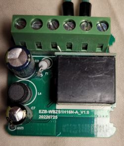
Here is the module designation CB3S W601 and only 4 pinouts
And here even better, because it is mysterious: T34 2133K9T4J X10LUC
On these devices you can upload OpenBeken , which supports:
Quote:
- BK7231T (WB3S, WB2S, WB2L, etc) - BK7231N (CB2S, CB2L, WB2L_M1, etc) - T34 (T34 is based on BK7231N) - BL2028N (BL2028N is a Belon version of BK7231N) - XR809 (XR3, etc) - BL602 (SM-028_V1.3 etc) - LF686 (flash it as BL602) - W800 (W800-C400, WinnerMicro WiFi & Bluetooth), W801 - W600 (WinnerMicro chip), W601 (WIS600, ESP-01W, TW-02, TW-03, etc) - LN882H WIP platform, see sample device teardown and flashing
ra_dzik wrote:
Here is the module designation of the CB3S W601. and only 4 pinouts
CB3S is BK7231N. The leads for programming are compatible with WB3S and TYWE3S. You can solder four wires (ground, 3.3V, RX and TX) and upload the OBK, here flasher: https://github.com/openshwprojects/BK7231GUIFlashTool Similar to here, only you select BK7231N in the flasher:
Before programming. programming watch the entire video
ra_dzik wrote:
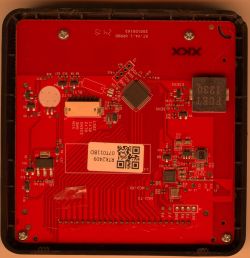
And here it gets even better, because it is mysterious:
T34 2133K9T4J X10LUC
T34 is also supported by OBK, you program it as BK7231N.
To program you have to solder four wires (RX,TX, 3.3V and GND), just not sure where to solder them. But there are 4 soldering points on the board... I suggest using the method of elimination. 1. check where the ground goes from the mother board, probably the ground has a large copper pad, this pad which is connected to it will be ground, GND 2. then you look for 3.3V, you can find it on the other pole of the capacitor which is between 3.3V and ground or look where from the other board 3.3V is connected, but by eye I can already see that probably 3.3V is here: 3. then there are 2 points left and there's the question which is TX and which is RX - but that's only two options, I'd try randomly connecting RX and TX first and then if the flasher doesn't move, I'd swap them places and that's it....
(sorry for the English reply) I also have a T34 on a 1CH WiFi smart switch and identified a bunch of pins that seem to be GND or 3.3V. Any hunch what would be good candidates for the TX/RX pins?
Shucks, my hands are falling off.... I bought a set of switches I specifically indicated I wanted this model and got....mix!
This is why I think that if someone wants to do a smart home with more devices, it's better to give up WiFi and go for ZigBee. I've done an article on PHP-based automation Link , but I recommend you read the first two paragraphs where my opinion is why ZigBee and not WiFi.
@krzbor everything has pros and cons, I prefer when the devices are available and controllable also when the main Home Assistant server is not available, as well as I use the communication directly between the devices (without the participation of HA), I do not like such a centralization that one hub is responsible for everything, but nevertheless I see that the solution presented by you is in some respects very simple and convenient.
I don't like such centralisation that one hub is responsible for everything
I agree - I am against integration of everything based on HA. If something goes wrong (e.g. HA or hardware failure) then we lose everything including e.g. heating. Therefore, in my opinion, it is best if we have a dedicated computer with MQTT - such an RPi will suffice. Once the MQTT configuration is stabilised, we make a copy of the SD card on the desktop computer, and additionally make a clone of this card necessarily with a check that the clone works. We have a good chance that such a thing without any update will work for 10 or even more years. A possible failure is also easy to reproduce - after all, there is no data on the MQTT server to automate. Instead of the point-to-point communication you mentioned, we can do point->MQTT->point automation. This won't compromise reliability, plus it will allow integration of points made with different technologies: Ethernet, WiFi, ZigBee. Here's an example - we're doing floor control. We can build our own actuator controller based on WiFi or Ethernet, which will have its own logic, but the room temperatures will be taken from the ZigBee sensors installed in each room. In addition, this default control logic can be modified by appropriate MQTT messages sent from the HA, for example. If the HA 'dies' the system will operate autonomously on its parameters.
Respectful @p.kaczmarek2 well I with all due respect wanted to buy a coffee, but this forum does not support blik, only, some American (haaa tfuuu) PayPal, I ask the moderation to expand the forms of payment, and the esteemed gentleman to provide an account number for a symbolic coffee.
Thank you very much, write me a PW and I will give you the details. The paypal comes from the fact that the whole initiative of making IoT comes mainly from the great interest of people from abroad on the English-language Elektroda website. It is also worth looking there sometimes, the community is very active: https://www.elektroda.com/ And the funds raised go to further development of the firmware including support for further platforms.
>>20942489 Well, I've got quite a bundle with it in the version with CB3S - it requires soldering the chip or, as I saw on some video, the chip next to it, because otherwise you can't program CB3S, because this chip next to it blocks I unfortunately don't have such a skill, to solder one of these two and not break anything I tried without soldering, but it says that it cannot communicate with the chip Is there any way to do this?
With the T34 version - the chip has the leads underneath the chip, you can't see the legs on the side, so geez I can't identify which lead is RX and which is TX, even though on the datasheet it is described as pins 25 and 26, the tracks go from under the chip and I don't know exactly how to identify this
If you have devices which are not listed here: https://openbekeniot.github.io/webapp/devicesList.html Have packaging for them (for pictures), and screenshots of where they were bought, and you are able to cover shipping both ways then I can personally flash them, but free flashing I offer only for one piece of each model because by the way I make a teardown entry on the forum. For larger quantities a contractual issue.
Additionally, as it happens with flashing, I can never give 100% certainty that a device will run until I try it myself.
ra_dzik wrote:
Well, I've got quite a bite out of that with the CB3S version - it requires soldering out the chip, or as I saw on some video, the chip next to it, because otherwise you can't program the CB3S, because the chip next to it blocks I unfortunately don't have that kind of skill, to unsolder one of these two and not break anything I tried without unsoldering, but it says that it can not communicate with the chip Is there any way to do this?
Check with a multimeter where this path goes from RX or there TX and find a place convenient to cut it temporarily.
I have also seen that some people use OTA flashing, but it is per-build (i.e. until someone downloads 2MB of batch from one of the devices of a given series, it will not flash the others).
Mate @krzbor actually had some other idea for it, but I haven't tried it myself and I don't know if it will work
ra_dzik wrote:
With the T34 version - the chip has the leads under the chip, you can't see the feet on the side, so geez I can't identify which lead is RX and which is TX, despite the fact that on the datasheet it is described as pins 25 and 26, the tracks go from under the chip and I do not know exactly how to identify it
As I wrote - as long as these 2 pads are RX and TX then you can forcefully, by trial and error guess. You determine VDD (e.g. from the mother board), determine where the ground is, then you are left with two options, if it doesn't move then you swap RX and TX and then it must move.
Worse, if it's not RX/TX at all, then it's a very hard situation.
✨ The discussion revolves around identifying the TX, RX, VCC, and GND pins on the CB3S W601 and T34 models, particularly after the user received incorrect switches. The CB3S W601 is identified as using the BK7231N chip, which can be programmed with OpenBeken (OBK) firmware. Users suggest soldering four wires (GND, 3.3V, RX, TX) for programming, with advice on locating these pins through methods of elimination. The T34 model is also compatible with OBK, but users express difficulty in identifying the correct pins due to their placement under the chip. Some users recommend using a multimeter for tracing connections and mention the possibility of OTA flashing. The conversation also touches on the preference for ZigBee over WiFi for smart home devices due to reliability concerns. Generated by the language model.
TL;DR: Four pins are all you need to flash CB3S/T34 (3.3V, GND, RX, TX). "T34 is also supported by OBK." Use BK7231GUIFlashTool; if flashing stalls, swap RX/TX. [Elektroda, p.kaczmarek2, post #20942489]
Why it matters: This FAQ helps makers identify TX/RX/VCC/GND and reliably flash CB3S/T34/W601 hardware without bricking, using tools that actually work, fast.
How do I find TX/RX/VCC/GND on a CB3S (BK7231N) board?
Trace GND first via continuity to the large copper pour. Locate 3.3V on the decoupling capacitor opposite GND or from the baseboard feed. The two remaining pads are RX and TX; connect them to a 3.3V USB‑UART. If the flasher doesn’t start, swap RX and TX. CB3S programming pads align with WB3S/TYWE3S. [Elektroda, p.kaczmarek2, post #20942489]
What’s the pinout story for Tuya T34—are UART pads exposed?
T34 uses BK7231N and is supported by OpenBeken, but some boards don’t route RX/TX to accessible pads. Check the Tuya T34 datasheet and consider accessing case-edge pins if present. “It seems that RX/TX is not routed out anywhere.” [Elektroda, p.kaczmarek2, post #20943747]
Can I flash Tasmota on CB3S/T34, or should I use OpenBeken?
Use OpenBeken for BK7231N/T34. OBK implements many Tasmota commands, Device Groups, and Tasmota JSON, so your workflows still fit. It also pairs easily with Home Assistant. “OBK is compatible with a large proportion of Tasmota commands.” [Elektroda, p.kaczmarek2, post #20943871]
Which flashing tool should I use for BK7231N/T34 and W600/W601?
Use BK7231GUIFlashTool. Older tools like bkWriter/hid_download_py are now deprecated. For T34, choose BK7231N in the flasher. Solder four wires: 3.3V, GND, RX, and TX. [Elektroda, p.kaczmarek2, post #20942489]
The flasher can’t communicate with CB3S—another chip is blocking UART. What now?
Isolate the module by temporarily cutting the RX/TX trace where it meets the co‑processor, then flash. Alternatively, per‑build OTA exists, but it only starts after about 2 MB downloads from one device. Results are hardware‑dependent and not guaranteed. [Elektroda, p.kaczmarek2, post #20946148]
How do I identify pins with a multimeter? Give me a quick 3‑step method.
Find GND by continuity to the largest copper pour.
Probe for 3.3V at the decoupling capacitor tied to GND.
What voltage levels should I use on UART for these modules?
Use 3.3V for VDD and UART logic levels. Do not connect 5V UART; that can damage the IC. Confirm 3.3V operation in the T34 electrical specifications. [T34 Module Datasheet]
Will OBK devices still work if Home Assistant goes down?
Yes. OBK supports direct device control and device‑to‑device communication, so loss of HA doesn’t stop basic operation. “I prefer when the devices are available and controllable also when the main Home Assistant server is not available.” [Elektroda, p.kaczmarek2, post #20943747]
Is ZigBee a better choice if I’m deploying many smart switches?
A contributor recommends a resilient approach: run a dedicated MQTT broker and combine ZigBee sensors with Wi‑Fi actuators. This enables autonomous control even if HA fails. It blends ecosystems via MQTT while maintaining reliability. [Elektroda, krzbor, post #20944182]
Can OpenBeken flash W600/W601 and CB3S modules?
Yes. OBK supports WinnerMicro W600/W601 and BK7231 families. CB3S is BK7231N; flash it as BK7231N using BK7231GUIFlashTool. [Elektroda, p.kaczmarek2, post #20942489]
Where can I find known pinouts or teardowns for similar devices?
Check the OpenBeken devices list for internals, wiring, and module mappings. It covers many WB3S, CB2S/CB3S, and T34 examples. [Elektroda, p.kaczmarek2, post #20942489]
I can’t solder tiny parts—can someone flash it for me?
An expert offered flashing one unit per model free if you cover both‑way shipping and share packaging photos. Larger batches are by arrangement, and success isn’t guaranteed until tested. [Elektroda, p.kaczmarek2, post #20946148]
For a T34 1‑channel switch, I see many 3.3V/GND pads—where are RX/TX?
If most pads are power or ground, RX/TX may not be exposed on that PCB. Check the T34 datasheet and consider module‑edge access. “It seems that RX/TX is not routed out anywhere.” [Elektroda, p.kaczmarek2, post #20943747]
Are BK7231 GUI flasher settings different for BK7231T vs BK7231N?
Yes. Select the correct target chip: BK7231N for CB3S/T34, BK7231T for WB3S/WB2S variants. Follow the linked video guidance before flashing. [Elektroda, p.kaczmarek2, post #20942489]