logo elektroda
logo elektroda
X
logo elektroda
Dostępna jest polska wersja

Czy wolisz polską wersję strony elektroda?

Nie, dziękuję Przekieruj mnie tam

Flashing yet another Mini Smart Switch with a T34, aka BK7231N chip

woessner 4959 14
ADVERTISEMENT
  • #1 21253441
    woessner
    Level 3  
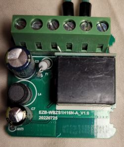
    This is for another Mini Smart Switch,
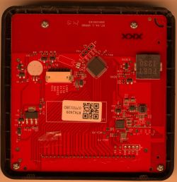
    this time with a T34 AKA BK7231N

    I did not read this forum thus I did not know about Tuya-Cloudcutter and thus flashed it the difficult way.
    Please try Tuya-Cloudcutter first!!


    Open Mini Smart Switch showing internal electronics and cover with external markings. The image shows the interior of a Mini Smart Switch with a visible relay and electronic components on a circuit board. PCB with electronic components and connected USB chip on a wooden surface.

    The LED is on 6
    The Switch input is on 14
    The Relay is on 15
    The Button on 24

    Code: JSON
    Log in, to see the code
  • ADVERTISEMENT
  • #2 21262684
    p.kaczmarek2
    Moderator Smart Home
    Thanks for sharing! Your template is now live on our devices list:
    Web interface showing a list of devices with a mini Smart Switch.
    See: https://openbekeniot.github.io/webapp/devicesList.html

    Good job with flashing it. Nice way of repurposing unused button pads. I hope it won't be too hard for other our readers as well. I'm worried to see more and more T34 devices around, Hopefully they won't totally replace easily-flashable CB2S/CB3S/etc modules.

    Added after 25 [seconds]:

    PS: Consider enabling powersave on this board or you may need to do this fix later:
    https://www.elektroda.com/rtvforum/topic3898805.html
    Helpful post? Buy me a coffee.
  • #3 21513370
    djramu
    Level 17  
    Hello.
    I have a problem. ;)
    I tried Tuya CloudCutter but couldn't manage. I think I prefer flashing via uart. With the GUI Flash Tool, can I change the firmware of this device? I tried to find the RX and TX pins but no success. Are You able to tell how You managed to flash this chip via uart?
  • ADVERTISEMENT
  • #4 21513754
    p.kaczmarek2
    Moderator Smart Home
    Do you have the exactly the same version as in the first post?

    It is possible to flash it with GUI Flash Tool, but you need to access UART pins.
    Helpful post? Buy me a coffee.
  • #5 21514467
    djramu
    Level 17  
    It goes like this. I would like to use uart but after soldering in the theoretical uart pins i don't have communication.

    Printed circuit board with electronic components, including an XGN relay.
    I tried with the pins marked in red.
  • Helpful post
    #6 21705064
    sp4rk1e
    Level 10  
    bought some of these so called 'Mini Smart Switches' from our favorite Chinese marketplace, For incredible 2.59€ per piece.

    Tuya Smart Switch 16A WiFi module with technical specs and customer ratings

    Mini Smart Switch housing showing technical specifications and connector labels

    again a new variant of this device. At least I've not seen such on this forum.

    Unfortunately with a T34 directly mounted on the board. Even with all of our beloved flash signals exposed somewhere on the board.

    Electronic module with relay, capacitors, and PCB antenna on wooden surface

    Green printed circuit board with visible traces and solder points

    Except TX. Holy crap no way to grab this pin except removing the whole chip :-(

    Relay module with electronic components on stone background

    for easier future use I handcrafted a small T34 flash adapter for my favorite USB ESP32 in circuit flash tool:

    Flashing yet another Mini Smart Switch with a T34, aka BK7231N chip

    Flashing yet another Mini Smart Switch with a T34, aka BK7231N chip

    my working OBK config is like this:

    
    {
      "vendor": "Tuya",
      "bDetailed": "0",
      "name": "Full Device Name Here",
      "model": "enter short model name here",
      "chip": "BK7231N",
      "board": "TODO",
      "flags": "64",
      "keywords": [
        "TODO",
        "TODO",
        "TODO"
      ],
      "pins": {
        "8": "WifiLED;0",
        "10": "TglChanOnTgl;1",
        "23": "Btn;1",
        "26": "Rel;1"
      },
      "command": "powersave 1",
      "image": "https://obrazki.elektroda.pl/1476559000_1759204894.jpg",
      "wiki": "https://www.elektroda.com/rtvforum/viewtopic.php?p=21705064#21705064"
    }
    
  • ADVERTISEMENT
  • #7 21705190
    p.kaczmarek2
    Moderator Smart Home
    This is the good approach. It's easy to tear off the QFN pad when using too large or not fixed in place wires.
    Helpful post? Buy me a coffee.
  • ADVERTISEMENT
  • #8 21714162
    p.kaczmarek2
    Moderator Smart Home
    I got the same as @sp4rk1e
    Electronic relay module with capacitors, ICs and terminal block

    Code: JSON
    Log in, to see the code


    Added after 1 [minutes]:

    https://github.com/openshwprojects/FlashDumps/commit/e6cc71df46ccbea39cd0eeee83b349599e2dc65e
    Helpful post? Buy me a coffee.
  • #9 21714175
    sp4rk1e
    Level 10  
    if everything else fails this board is a nice 3.3V power supply for other ESP32 projects after removing unnecessary parts. Of course setup must be completely isolated. At least I haven't seen a DIY power supply for the mains at that size yet. :-)
  • #10 21714179
    p.kaczmarek2
    Moderator Smart Home
    It wasn't that bad:
    Person holding a cardboard-mounted sensor connected to a breadboard and laptop
    but I probably should buy this:
    Green PCB adapter QFN32/QFN40 to DIP32/DIP40 with labeled pins and central chip pad.
    Helpful post? Buy me a coffee.
  • #11 21732349
    woessner
    Level 3  
    I bought six of them because it was quite easy to flash them last time but now I had the chips where the pins could not be accessed from the side :-(
    Hand-soldering tiny wires to the chip was a nightmare, though, but I did that on one of them and successfully flashed the firmware.
    Doing that on the five remaining ones --> no way!
    Thus I printed a jig to hold the chip.
    That worked amazingly!
    Thus I have to share the CAD files for that.
    Pink 3D-printed holder with a chip and thin soldered wires on sides
    Pink 3D-printed chip holder with connected wires and a separate chip module
    Set of Mini Smart Switch modules and circuit boards on a workbench
    PS: The LED is on 8
    Button on 10
    and Relay on 26
    Please find attached STL and Inventor files. If you need a different CAD file format, just send me a PM.
    Attachments:
    • T34_Tuya.zip (679.06 KB) You must be logged in to download this attachment.
  • #12 21732366
    p.kaczmarek2
    Moderator Smart Home
    Interesting, I didn't think about such approach.
    CAD files could be useful, zip them and attach, or I can help if it's not working for you. Nice design.
    Helpful post? Buy me a coffee.
  • #13 21732443
    woessner
    Level 3  
    >>21732366
    Zip files worked!
    The print is accurate enough to give a good alignment, and on some of them I had to press down a bit on the 3D print to get a good contact with the needle tips, but other than that, no problem.
    I did add a bit of leaded solder on the chip pads before putting them in the jig; that might have helped a bit with the contact too, and I had to do that anyway to reflow them after programming.
  • #14 21742615
    jacgerri
    Level 4  
    Hi all,
    I've exactly the same Mini Smart Switch with a T34 but I can't flash it because I don't know which version to take. Tuya app tells v1.3.18 but it does not exist in OpenBK7231N_UG_1.18.206.bin. Tried a lot of versions like 1.2.1, 1.1.5, 1.1.6, 1.1.7, but always get the message:

    ================================================================================
    [!] The profile you selected did not result in a successful exploit.
    ================================================================================

    Can someone help me with this, maybe?
  • #15 21760986
    nelliug54
    Level 6  
    Hello, I received the same item from AliExpress, and after connecting pin 26 (TXD) with a thin copper strip secured with thermal adhesive, I verified that it made contact with a multimeter (3.3 V) and was able to program the T34. (Note: power from a lithium battery is much better for programming.) Now I'm struggling to get the 433 MHz RF working. The receiver's TX output is connected to P6 (PWM0), but I can't figure out how to configure this input on the T34. The transmitter that came with the mini smart switch sends a code using the EV1527 chip, which is quite common: SYNC - 20 address bits - 4 data bits. Could someone help me configure the RF to work properly?

Topic summary

✨ The discussion focuses on flashing a Mini Smart Switch equipped with a T34 (BK7231N) chip. The original poster shared a custom device template including pin assignments: LED on pin 6, switch input on pin 14, relay on pin 15, and button on pin 24. They recommend using Tuya-Cloudcutter for easier flashing, as they initially used a more complex manual method. Responses confirm the template is now included in a public devices list and highlight concerns about the increasing prevalence of T34 devices replacing more easily flashable modules like CB2S/CB3S. Users report difficulties locating UART pins for flashing via the GUI Flash Tool, with one user unable to establish UART communication despite soldering on marked pins. It is confirmed that UART flashing is possible but requires correct identification of UART pins. A power-saving mode recommendation is also mentioned to avoid later fixes.
Generated by the language model.

FAQ

TL;DR: Flashing T34/BK7231N mini switches is doable: 3 key pins mapped (LED=8, BTN=10, RELAY=26). "That worked amazingly!" [Elektroda, woessner, post #21732349]

Why it matters: This FAQ helps DIYers quickly pick a working flashing path, pin map, and safe handling steps for T34-based mini switches.

Quick Facts

What is the simplest way to flash this T34/BK7231N mini switch?

Try Tuya-Cloudcutter first. The original poster stressed this before resorting to the hard-wired method. If Cloudcutter fails, move to UART flashing. This two-step approach saves time and avoids risky soldering on QFN pads. [Elektroda, woessner, post #21253441]

Which pins are mapped on the early Mini Smart Switch revision?

Early boards used: LED=6, Switch input=14, Relay=15, Button=24. This template worked after a direct flash. Use it as a starting point if your PCB matches the photos from that report. "Please try Tuya-Cloudcutter first!!" still applies before soldering. [Elektroda, woessner, post #21253441]

Which pins are mapped on the newer revision seen later in the thread?

A later batch reported: LED=8, Button=10, Relay=26. The contributor aligned spring needles with a printed jig for reliable contact and repeated flashes across units. That fixture reduced risk versus hand-soldering hair-thin wires. [Elektroda, woessner, post #21732349]

Can I flash it with the GUI Flash Tool over UART?

Yes, if you can access the UART pads. The maintainer confirmed GUI flashing works once RX/TX are reachable on your exact board revision. If Cloudcutter profiles fail, switch to UART and proceed. [Elektroda, p.kaczmarek2, post #21513754]

Where is TXD on some T34 boards, and how do I grab it?

On some units, TXD is pad 26. One user bonded a thin copper strip with thermal adhesive, verified 3.3 V with a multimeter, and programmed successfully. They also noted a lithium cell gives cleaner power during flashing. [Elektroda, nelliug54, post #21760986]

What if TX isn’t exposed—am I stuck?

A contributor found every flash signal except TX exposed, calling it “no way to grab this pin except removing the whole chip.” In that edge case, use a fine-pitch adapter or in-circuit jig to avoid lifting QFN pads. [Elektroda, sp4rk1e, post #21705064]

How do I avoid ripping QFN pads when wiring the T34?

Keep wires short, fixed, and strain-relieved. An experienced flasher warned, “It’s easy to tear off the QFN pad when using too large or not fixed in place wires.” A simple adapter or jig helps. [Elektroda, p.kaczmarek2, post #21705190]

Is there a no-solder or low-solder method to program several units?

Yes. A 3D-printed alignment jig with spring needles worked across multiple devices. The user pre-tinned chip pads lightly, pressed the jig to ensure contact, and repeated successful flashes on a batch of five remaining switches. [Elektroda, woessner, post #21732349]

Cloudcutter keeps failing with my Tuya build—what should I do next?

If your selected profile fails, pivot to UART flashing. The maintainer explicitly said GUI flashing is possible once UART pads are accessible. This bypasses profile mismatches while keeping your device recoverable. [Elektroda, p.kaczmarek2, post #21513754]

Do I need to enable power saving after flashing OpenBeken?

Yes. The maintainer recommended enabling powersave on this board family to avoid a later hardware fix. Add a powersave command after first boot to improve stability and reduce idle consumption. [Elektroda, p.kaczmarek2, post #21262684]

What OpenBeken template works on the adapter-based variant?

A shared OBK config set WifiLED=8, Toggle=10, Button=23, Relay=26, plus “powersave 1.” This template booted correctly on the T34/BK7231N board and supports single-channel relay control. [Elektroda, sp4rk1e, post #21705064]

How do I hook up the 433 MHz EV1527 remote on this switch?

One user confirmed the RF receiver’s TX goes to P6 (PWM0). Their remote uses EV1527 framing: SYNC + 20 address bits + 4 data bits. Configure T34 to treat P6 as the RF input and verify clean 3.3 V signaling. [Elektroda, nelliug54, post #21760986]

Is there any firmware/config dump that confirms key pins?

Yes. A posted configuration block shows module=T34 with netled1_pin=8 and rl1_pin=26 among other parameters. Use it to cross-check your pin mapping when templates appear inconsistent across batches. [Elektroda, p.kaczmarek2, post #21714162]

What’s the cost–benefit of these boards for projects?

At about €2.59 each, they are cost-effective for Wi‑Fi relay experiments. Even if flashing fails, one contributor repurposed the board as a compact isolated 3.3 V supply after removing unused parts. [Elektroda, sp4rk1e, post #21714175]

What are Tuya and OpenBeken in this context?

Tuya is the stock platform on these switches; Cloudcutter targets it for OTA exploits. OpenBeken (OBK) is the community firmware used here to replace Tuya on BK7231 devices. OBK templates and commands appear throughout the thread. [Elektroda, sp4rk1e, post #21705064]

How do I flash via UART safely on a T34 board (quick 3-step)?

  1. Secure the PCB; power at 3.3 V; align a small adapter or jig.
  2. Connect RX/TX (TXD may be pad 26); enter flash mode; use GUI Flash Tool to write OBK.
  3. On first boot, set pins per template and run “powersave 1.” [Elektroda, sp4rk1e, post #21705064]
Generated by the language model.
ADVERTISEMENT