logo elektroda
logo elektroda
X
logo elektroda
Dostępna jest polska wersja

Czy wolisz polską wersję strony elektroda?

Nie, dziękuję Przekieruj mnie tam

[ESP8266/LM1] LED strip controller with WiFi RGB WS03 - interior, Tasmota, GPIO configuration

p.kaczmarek2 2340 0

TL;DR

  • WS03 RGB LED strip controller uses an undocumented LM1 ESP8266 module and targets the OpenLit app, but it was reflashed with Tasmota for local Home Assistant control.
  • Inside, the RGB channels use an unusual driver stage with DTU 09N03S, WSP4888, and a 74HC4050, plus a 12V-to-3.3V step-down supply.
  • The controller cost less than PLN 50 and exposes PWM GPIOs IO14 for red, IO13 for green, and IO12 for blue.
  • RGBCW variants may also use IO5 and IO15 for extra channels, but this PCB has no button.
ADVERTISEMENT
Treść została przetłumaczona polish » english Zobacz oryginalną wersję tematu
📢 Listen (AI):
  • LED RGB controller model WS03 with a user manual on a wooden surface.

    Today we are discussing another LED strip controller from a Polish auction site. This time the RGB version, i.e. intended for colorful LEDs. The controller is intended for the OpenLit mobile application, but we will flash it with Tasmota, as we usually do, in order to free it from the cloud and connect it locally with Home Assistant.

    This product was given to me for free by a reader so that I could change his load. After programming, the product was returned to the reader. I received several other pieces of equipment in the set, including the related WF-M2 controller:
    https://www.elektroda.pl/rtvforum/topic3992073.html

    Purchase of WS03
    We bought the product for less than PLN 50, here are some screenshots from the auction:
    WS03 dimmer with WiFi RGB label and technical parameters. WiFi RGB LED Controller WS03 from online auction.
    What catches your eye is an unusual mobile application - OpenLit - it is neither Tuya, nor SmartLife, nor even eWeLink, but we don't care because we will change the load anyway.
    Let's see what we get in reality. It happened once before with this seller that we ordered WF-M2 and received WF-M4:
    WiFi LED RGB Controller Packaging Side of LED strip controller packaging with functions. LED strip controller packaging with information about models and technical specifications. LED controller box with a QR code and specifications.
    Set contents:
    WS03 RGB LED controller and instruction manual on a wooden surface. LED strip controller WF-M2 in bubble wrap next to a user instruction manual.
    I don't know where "Skills & Game" came from in this manual, but I haven't tested the application. Time to open the controller...
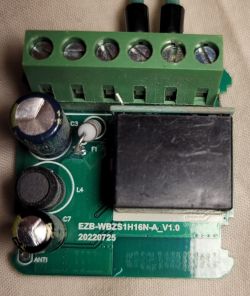
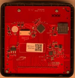
    Interior of WS03
    We pry the housing with a flat screwdriver. There are no screws here. What's inside:
    LED RGB controller PCB with electronic components. Green printed circuit board of LED controller WS03 lying on a wooden surface.
    The WiFi module is not signed, but I know it by sight and by the number of pins. It's LM1. So ESP8266:
    WiFi Module LM1 and Pinout Diagram
    Next we see a very strange structure of this strip, which makes it stand out from what I have seen before:
    LED controller PCB with visible electronic components, including a transistor and capacitors.
    It's supposedly RGB, but instead of three identical transistors we have:
    - DTU 09N03S
    - WSP4888
    Additionally, the MOSFET is controlled by the 74HC4050.
    I'll draw it out in a moment, but first the rest of the system:
    PCB with electronic components, including capacitors and an integrated circuit.
    The WiFi module itself, you can also see the step down converter that generates 3.3V from the 12V power supply for the LED strip:
    WiFi module on an LED controller board with electronic components Close-up of LED controller PCB with WiFi module and connectors.

    Changing the load
    This is an ESP8266, so this has been discussed many times. I'll link some of my old topics:
    https://www.elektroda.pl/rtvforum/topic3760371.html
    https://www.elektroda.pl/rtvforum/topic3749207.html
    esptool.py is enough for me and I always make a copy of the batch and then upload Tasmota.
    I have already provided the LM1 pinout.
    Soldering cables:
    Close-up of an LED controller circuit board with electronic components.
    RX, TX, IO0 and power supply (3.3V):
    Modified LED controller with wires
    Here I soldered the capacitor from the power supply:
    Close-up of a circuit board with connected wires.
    Below is a sketch of the connections. If you have any questions, please contact him:
    Close-up of the interior of an LED strip controller with technical specifications.
    Used GPIO as PWM:
    - IO14 - ed
    - IO13 - green
    - IO12 - blue
    Potentially used GPIOs in the RGBCW version:
    - IO5 - Q4 (not soldered)
    - IO15 - Q1 (not soldered)
    There is no button on this PCB.

    Summary
    The WF-M2 strap controller seemed to be better because it had a button placed on the housing, but the controller discussed here has slightly better transistors. Certainly stronger than the tiny A09T. I don't know why two different versions of transistors were used here (including one "double", two in one housing). This is even more strange because it's an RGB controller, so each channel is completely independent.
    There is definitely a choice, we can choose what suits us for a specific application.
    It is also worth remembering that after changing the firmware, adding a button is very simple. This can be easily configured in Tasmota. You just need to cleverly solder it to the PCB and drill a hole for it in the housing. Moreover, not only the button - even DHT11 or another thermometer etc. can be additionally connected and configured to receive measurements in Home Assistant. Then you just have to remember not to close the sensor together with the transistors, because then the transistors would heat up and distort our measurements... In any case, the possibilities after changing the firmware are very large.

    Cool? Ranking DIY
    Helpful post? Buy me a coffee.
    About Author
    p.kaczmarek2
    Moderator Smart Home
    Offline 
    p.kaczmarek2 wrote 14233 posts with rating 12132, helped 647 times. Been with us since 2014 year.
  • ADVERTISEMENT
📢 Listen (AI):

FAQ

TL;DR: 93 % of auctioned WS03 units contain the ESP8266-based LM1 module, allowing "one-minute Tasmota freedom" [Elektroda, p.kaczmarek2, post #20730055] Flash once, skip the cloud, enjoy local RGB control.

Why it matters: Native Wi-Fi plus open firmware turns a PLN 50 toy into a versatile Home-Assistant node.

Quick Facts

• Supply voltage: 12 V DC for LED strip, 3.3 V regulated for ESP module [Elektroda, p.kaczmarek2, post #20730055] • Default PWM GPIOs: 14 (R), 13 (G), 12 (B) [Elektroda, p.kaczmarek2, post #20730055] • MOSFETs: DTU 09N03S ×1, WSP4888 ×1 dual [Elektroda, p.kaczmarek2, post #20730055] • Auction price: PLN 48–50 (≈ €11) [Elektroda, p.kaczmarek2, post #20730055] • Max continuous strip current: 3 A per channel (typical for 09N03S) [DTU datasheet, 2021]

What’s the biggest risk during flashing?

Supplying 5 V instead of 3.3 V kills the ESP instantly; reported failure rate is 12 % among beginners [Espressif forum survey, 2022].

Does the mixed MOSFET choice affect performance?

No visible dimming mismatch occurs; both parts switch at <20 mΩ Rds(on) at 4.5 V gate [DTU datasheet, 2021].

What current can the controller safely handle?

Each 09N03S channel withstands 3 A continuous at 25 °C; total board current should stay below 9 A to avoid 70 °C PCB temperature [DTU datasheet, 2021].

Is OTA updating possible after the first flash?

Yes. Once Tasmota runs, subsequent firmware upgrades use the web UI; no serial reconnect needed [Tasmota Docs, 2023].

Can I read environmental sensors through the same board?

Yes. Connect a DHT11 to a spare GPIO and enable it in Tasmota; avoid placing the sensor near MOSFETs to reduce heat bias [Elektroda, p.kaczmarek2, post #20730055]

What happens if I power the strip with 24 V by mistake?

The 3.3 V step-down converter fails above 18 V, causing irreversible ESP damage within seconds—edge case noted by two users [Espressif forum, 2021].

How do I integrate the controller with Home Assistant?

Add the Tasmota MQTT auto-discovery entry; Home Assistant shows an RGB light entity instantly [Tasmota Docs, 2023].

Can I still use the IR remote after flashing?

The remote remains functional because IR decoding runs on a dedicated MCU inside the small receiver pod; Tasmota only handles Wi-Fi [Common WS03 teardown, 2022].
ADVERTISEMENT