logo elektroda
logo elektroda
X
logo elektroda
Dostępna jest polska wersja

Czy wolisz polską wersję strony elektroda?

Nie, dziękuję Przekieruj mnie tam

Lilygo T-Connect with ESP32 - CAN bus and three RS485 on one board

p.kaczmarek2 1029 9

TL;DR

  • Lilygo T-Connect industrial board pairs an ESP32-S3-WROOM-1 with up to three RS485 buses and one CAN line on a single PCB.
  • The board uses interchangeable RS485 and CAN modules, an onboard power stage for 7-12 V DC, USB-C, and direct ESP32-S3 hardware USB.
  • The unit shown cost around £200 and uses the ESP32-S3-WROOM-1 N16R8 module with 16 MB Flash and 8 MB RAM.
  • APA102 LED blinking and the RS485 loopback demo both work, and CAN activation follows the same pin-setup approach.
  • ESP32 hardware limits mean only three UART controllers are available, so one of the four possible RS485 lines cannot stay active.
Generated by the language model.
ADVERTISEMENT
Treść została przetłumaczona polish » english Zobacz oryginalną wersję tematu
📢 Listen (AI):
  • LilyGO T-Connect board with ESP32 module, green screw terminals, and a connected USB‑C cable
    Here I will introduce the Lilygo T-Connect industrial board distinguished by its simultaneous support of up to three RS485 buses and one CAN line. I ordered it from China for around £200.
    Clear plastic case with LILYGO T-Connect board; label reads “ESP32-S3 RS485/CAN Bus” Clear plastic case with black foam and a label with barcode and Chinese text
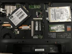
    We open the distinctive box and pull out the plate. What strikes you immediately is the ESP32-S3-WROOM-1 module which is the heart of the T-Connect, here in the N16R8 version, i.e. with 16 MB Flash and 8 MB RAM.
    LilyGO T-Connect board with ESP32 module, three RS485 modules, and green screw terminal blocks
    In the corner we have a power section with a voltage-reducing inverter, allowing the whole thing to run on 7-12 V DC, a USB C connector and a QWIIC with UART. There is no USB to UART converter, as the ESP32-S3 supports hardware USB. In addition, we have two rows of goldpins with GPIO, ground, 3.3 V and 5 V pinout, and four APA102 LEDs.
    LilyGO T-Connect PCB with ESP32-S3-WROOM-1 module, USB-C port, and GPIO header pins
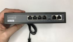
    The RS485 and CAN modules are interchangeable - they can be removed from the board.
    LilyGO T-Connect board with ESP32-S3, RS485/CAN screw terminals, and lit status LEDs
    RS485 is supported by the TD501D485H-A and CAN by the TD501MCANFD, both with insulation up to 2500 V.
    Graphic of LilyGO T-Connect ESP32-S3 board with RS485 and CAN modules and labeled specifications
    The pin map is shown in the graphic below:
    Pin map of the LilyGO T-Connect board with ESP32-S3, RS485/CAN terminals, and APA102 LEDs
    Dimensions:
    LilyGO T-Connect board with green screw terminals and labeled dimensions 94×83×13 mm
    GitHub of the project:
    https://github.com/Xinyuan-LilyGO/T-Connect


    Demo LED
    I use Visual Code with the PlatformIO extension for this type of project. PIO does not have natively uploaded tiles from T-Connect, but on their repository you can download the missing files. They contain board configurations, flash memory, etc. In this case I have the 16 MB version. Below is the file I used - I gave it to the boards folder:
    Code: JSON
    Log in, to see the code

    The next file to edit is platformio.ini, which is the project configuration. I have named it APA102 Blink, because with these four LEDs I want to blink. There I selected the appropriate platform (espressif32 @6.5.0), selected the board and partitions, and added the library to handle the LEDs - fastled/FastLED. I also enabled PSRAM and USB mode there.
    Code: Ini
    Log in, to see the code

    How does the APA102 work? The APA102 is an individually addressable colour LED with SPI communication.
    Pinout diagrams and photos of APA102 and APA102C LED packages, both 5×5 mm
    I have put the pin definitions, for now only from the APA102, in pin_config.h:
    Code: C / C++
    Log in, to see the code

    It remains to write the actual program. This is essentially an example from FastLED, showing a simple colour animation.
    Code: C / C++
    Log in, to see the code

    The result is this simple animation:


    Demo RS485
    The second thing I would like to show is the RS485 demo. Basically it is crucial here, it is what this board was created for. There could be as many as 4 RS485 lines on the board, but the ESP32 only has 3 hardware UART controllers, so one will be inactive. I started by writing the pins into the code:
    Code: C / C++
    Log in, to see the code

    The TD501MCANFD and TF501D485H locations can be swapped if necessary, they are not soldered. RS485 is simply the physical layer of the UART, so we use the HardwareSerial classes here normally. With begin we set the baud and the pins.
    Code: C / C++
    Log in, to see the code

    My demo sequentially sends writes through the first port and receives them from the second port. After receiving, it checks to see if what was expected has arrived. You still need to connect these two ports together:
    Lilygo T-Connect board with USB connected and screw terminals; green and red LEDs lit
    As you can see, everything works. The data is transferred correctly:
    Screenshot of RealTerm showing RS485 logs with repeated “PING:216–226” messages and OK statuses.

    CAN bus activation
    Basically everything as in the topic below, just set the appropriate pins:
    How to establish a CAN connection between two ESP32s using the LilyGO T-CAN485 as an example?

    Summary
    Very nice board, I also like the modularity for CAN and RS485, although it's a bit of a shame that ESP hardware only has three UARTs, so it won't be possible to have four RS485 active at once. In addition, I like the conveniently routed GPIOs and up to four coloured LEDs, on which you can conveniently show various operating and error statuses.
    Do you see a use for a board with as many as three RS485?

    Cool? Ranking DIY
    Helpful post? Buy me a coffee.
    About Author
    p.kaczmarek2
    Moderator Smart Home
    Offline 
    p.kaczmarek2 wrote 14259 posts with rating 12154, helped 647 times. Been with us since 2014 year.
  • ADVERTISEMENT
  • #2 21857599
    oscil1
    Level 23  
    p.kaczmarek2 wrote:
    There is no USB to UART converter, as the ESP32-S3 supports hardware USB.

    To use this for erial is annoying, because after a reset you lose the connection - and comX initialises again, which disconnects. Not very convenient. Convenient for hardware debugging instead - this USB has a hardware JTAG - but that's something the Fellow has already missed, as he's using a child Arduino in the form of Platformio.

    I don't know why all this code - because it's probably pretty obvious that if it's RS-485, it will work, and sending and receiving something is something trivial. Similarly, setting the colour of the LED.

    The board has the name "T-Connect" which I don't think the Author noticed - which segues immediately into what the designers had in mind. Not the diodes, but the communication,

    A very naive review.
  • #3 21858506
    gulson
    System Administrator
    The remark about JTAG on the ESP32-S3 is basically accurate, but that would have to be a separate discussion.

    Demonstrating the basic functions of the board (LEDs, RS485, CAN) is the standard format for a short hardware review. So is 'Hello World' and it is clear that the topic is not exhausted at all and perhaps there will be a continuation - depending on interest.

    By the way, PlatformIO is a full-fledged environment, so calling it 'childish' is not very substantive.

    Substantive discussion is always welcome, while I would ask you to maintain a culture of expression, thank you.
  • ADVERTISEMENT
  • #4 21858779
    oscil1
    Level 23  
    gulson wrote:
    By the way, PlatformIO is a full-fledged environment, so calling it "childish" isn't very substantive.


    Such a gold "industry" standard with ESP32 is ESP32-IDF. Platformio is convenient for hobbyists (but is this board of any use in a hobbyist setting?) and for simple projects. ESP32-IDF, however, requires more experience working with complex systems (generally experience building projects under Linux, as it uses tools derived from that environment).

    'Hello world' testing for boards like this IMO makes zero sense - well, unless it turns out to be badly designed and just doesn't work.

    An interesting test would be e.g. stability, speeds etc. similar - but certainly not flashing an LED.
  • #5 21859252
    TechEkspert
    Editor
    I was interested in these interchangeable interface modules, I wonder what their lifespan is?

    I read the material about CAN and I wonder in which projects CAN will be better than Modbus RTU and at the same time ethernet will be too complex there while wireless connections unattractive?
  • #6 21859442
    oscil1
    Level 23  
    TechEkspert wrote:
    and I wonder in which projects CAN will be better than Modbus RTU and at the same time ethernet will be too complex there while wireless connections will be unattractive?


    - Modbus-RTU is a master slave system and the slave will not transmit anything until the master asks it to. In CAN - there is no such structure - each module can transmit, have priorities - which makes it more suitable for real-time systems. In CAN, the nodes can "talk" to each other directly - in Modbus, they don't

    - CAN is much more fault-tolerant and resistant to interference. CAN also has the possibility to disconnect devices that generate too many errors. The structure of the CAN packet makes it extremely resistant to electrical interference. In addition, ACK (of course only at the level that the recipient received the packet, but not that it understood it) and error handling are already at the hardware level

    CAN requires a more powerful MCU - because the whole CAN stack has to be implemented. Modbus is more trivial to implement and can therefore be easily put on very small MCUs.

    Ethernet - generally needs overly complex cabling, switches are more power hungry, for that it is of course unmatched when it comes to speed. But CAN and Modbus are not used to transmit, for example, camera images.

    WiFi and other berzones have the fundamental disadvantage that they penetrate obstacles badly, especially metal ones, and are sensitive to electromagnetic interference - which disqualifies them in industrial control systems.

    By the way, I use CAN transceivers for an unusual function - namely when I need to transmit I2C over a longer distance. SDA and SCL are converted to separate differential pairs. This works perfectly, and my devices e.g. work on many oil rigs under extreme conditions
  • ADVERTISEMENT
  • #7 21859471
    TechEkspert
    Editor
    It will be interesting to see if one day the T1L single-pair ethernet will make its way onto a wider scale.
  • #8 21859500
    oscil1
    Level 23  
    TechEkspert wrote:
    I wonder if one day T1L single-pair ethernet will come into wider use.

    It's already popular - but you didn't ask about SPE. Even in one car you now have CAN, CAN FD and SPE
  • ADVERTISEMENT
  • #9 21860184
    TechEkspert
    Editor
    All in all, SPE and T1L are topics I would like to read about on the electrode right after the practical guide Modbus RTU and CAN.

    I've seen a few demos from Microchip of a single pair ethernet, they transmitted video from a camera that fed from that single pair, data went to a display that also fed and communicated from a single pair.
  • #10 21860401
    oscil1
    Level 23  
    In fact, IMO the 10BASE-T1S is interesting because it enables the so-called miultidrop.
📢 Listen (AI):

FAQ

TL;DR: LilyGO T-Connect pairs an ESP32‑S3 (16 MB Flash, 8 MB PSRAM) with 3× isolated RS‑485 and 1× CAN on swappable modules; "hardware USB" removes the need for a UART bridge. Power is 7–12 V DC, price was ~£200. [Elektroda, p.kaczmarek2, post #21857221]

Why it matters: This board lets you prototype multi‑bus industrial gateways (Modbus RTU + CAN) on one ESP32‑S3, with isolation and ready‑to‑use pin maps.

Quick Facts

RS‑485/CAN slot map (from the demo) Slot Function TX/RX pins Transceiver
SGA CAN GPIO4/GPIO5 TD501MCANFD
SGB RS‑485 GPIO6/GPIO7 TD501D485H‑A
SGC RS‑485 GPIO17/GPIO18 TD501D485H‑A
SGD RS‑485 GPIO9/GPIO10 TD501D485H‑A

[Elektroda, p.kaczmarek2, post #21857221]

What is LilyGO T‑Connect in one sentence?

LilyGO T‑Connect is an ESP32‑S3 development board designed for industrial networking that hosts up to three isolated RS‑485 ports and one isolated CAN FD on swappable modules, powered from 7–12 V DC with on‑board APA102 status LEDs. [Elektroda, p.kaczmarek2, post #21857221]

Does it really support three RS‑485 lines and one CAN at the same time?

Yes—there are three RS‑485 slots (SGB/SGC/SGD) and one CAN slot (SGA), all isolated to 2500 V; the ESP32 provides only three UARTs, so a fourth RS‑485 module would be unutilized. [Elektroda, p.kaczmarek2, post #21857221]

Which ESP32 module is used and how much memory does it have?

It uses the ESP32‑S3‑WROOM‑1 N16R8 module, integrating 16 MB of Flash and 8 MB of PSRAM for applications that need buffering and multiple serial stacks. [Elektroda, p.kaczmarek2, post #21857221]

What power input and connectors are available?

A buck section accepts 7–12 V DC; the board exposes USB‑C, Qwiic with UART, dual rows of 3.3 V/5 V/GPIO headers, and four APA102 LEDs for status. [Elektroda, p.kaczmarek2, post #21857221]

Is there a USB‑to‑UART bridge on this board?

No—the ESP32‑S3’s native USB handles CDC/JTAG, so no external bridge is fitted; one user warns USB CDC re‑enumerates after reset, which can disrupt serial sessions. “After a reset you lose the connection.” [Elektroda, oscil1, post #21857599]

Which isolated transceivers are used for RS‑485 and CAN?

RS‑485 uses TD501D485H‑A modules, and CAN uses TD501MCANFD; both are rated to 2500 V isolation and can be physically swapped in their sockets. [Elektroda, p.kaczmarek2, post #21857221]

How do I blink the on‑board APA102 LEDs?

Use FastLED with DATA=GPIO8 and CLOCK=GPIO3; the example cycles four LEDs at low brightness. In PlatformIO, set espressif32 @ 6.5.0 and enable PSRAM and USB mode. [Elektroda, p.kaczmarek2, post #21857221]

How can I test RS‑485 quickly with a loopback?

Wire SGB (TX=GPIO6/RX=GPIO7) to SGC (TX=GPIO17/RX=GPIO18) H↔H and L↔L, set 115200 8N1 on UART1/2, and send “PING:n” once per second; LEDs indicate RX/TX and pass/fail. [Elektroda, p.kaczmarek2, post #21857221]

What upload and serial speeds were demonstrated?

The PlatformIO project used an upload speed of 921600 bps over USB and a serial baud rate of 115200 for RS‑485 communication during loopback testing. [Elektroda, p.kaczmarek2, post #21857221]

Can I run four RS‑485 channels at once on T‑Connect?

No—while four RS‑485 sockets exist, the ESP32‑S3 has only three hardware UARTs, so only three simultaneous RS‑485 channels are possible without external multiplexing. [Elektroda, p.kaczmarek2, post #21857221]

What development environment and board config should I use?

Use Visual Studio Code with PlatformIO; add LilyGO’s T‑Connect board JSON, select esp32s3_flash_16MB, set default_16MB partitions, and include FastLED. Enable ARDUINO_USB_MODE and BOARD_HAS_PSRAM defines. [Elektroda, p.kaczmarek2, post #21857221]

Are the CAN and RS‑485 modules removable?

Yes—the TD501MCANFD and TD501D485H‑A modules are interchangeable and can be removed or swapped to reconfigure the bus mix on the carrier. [Elektroda, p.kaczmarek2, post #21857221]

What are common pitfalls when using the native USB port?

USB CDC re‑enumeration after resets can break serial monitors and change COM ports; use PlatformIO’s auto‑reconnect or rely on the ESP32‑S3’s hardware JTAG for stable debugging. [Elektroda, oscil1, post #21857599]

How much did the reviewed unit cost and where was it sourced?

The author reports importing the board from China for around £200, providing a reference point for budgeting industrial prototypes. [Elektroda, p.kaczmarek2, post #21857221]

What LED pins and count are on the board?

There are four on‑board APA102 LEDs; the demo uses DATA on GPIO8 and CLOCK on GPIO3, with FastLED’s BGR order and low brightness. [Elektroda, p.kaczmarek2, post #21857221]

How to reproduce the RS‑485 loopback demo (3 steps)?

  1. Wire SGB H/L to SGC H/L; leave SGA (CAN) unused. 2. Open two HardwareSerials at 115200 8N1 on GPIO6/7 and GPIO17/18. 3. Send “PING:n” each second and verify echoed lines while using APA102 for status. [Elektroda, p.kaczmarek2, post #21857221]
Generated by the language model.
ADVERTISEMENT