logo elektroda
logo elektroda
X
logo elektroda
Dostępna jest polska wersja

Czy wolisz polską wersję strony elektroda?

Nie, dziękuję Przekieruj mnie tam

Railway on-board computer from a Polish company - construction, interior and commissioning

p.kaczmarek2 2037 11

TL;DR

  • A railway on-board main computer/controller from a Polish company opens like a book and reveals a two-board internal layout with VGA, USB, Ethernet, and phone ports.
  • The hardware combines an EVOC single-board computer with a proprietary motherboard and a separate monitor board, plus a backup-power board with Li-FePO4 cells and power converters.
  • The computer identifies as EVOC 104-1649CLD2NA and shows an AMD Geode PCS 500 MHz CPU, DDR2 487 MB memory, and a 2 GB NANDrive.
  • It boots far enough to enter BIOS and detect a USB keyboard and Realtek RTL8139 networking, but Linux halts with a "System halted" error.
  • Two ANR26650M1A A123 3.3V 2300mAh Li-FePO4 batteries were found discharged to fractions of a volt, and the system is password-protected.
Generated by the language model.
ADVERTISEMENT
Treść została przetłumaczona polish » english Zobacz oryginalną wersję tematu
📢 Listen (AI):
  • Black PIXEL SmartPix controller case with IP and MAC labels, on a light tabletop
    Today, another curiosity from the electro-junk - a main computer/controller which, according to my information, was used on trains. I'll try to get it up and running here, get into the BIOS, etc. This time the presentation will be even more rich than usual, as I got this equipment in one and a half copies.
    Rear of a black computer module with VGA, two USB ports, and several multi-pin connectors
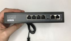
    The first thing that catches the eye is the VGA monitor output and two USB ports. On the other side we have two Ethernet ports and one telephone port. In addition, we have a connector suggesting a power supply, although the case information rules out that it's ATX - the expected voltage is 24V DC.
    Black electronic module with Ethernet ports (ETH0/ETH1) and a white multi-pin connector
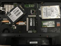
    The chassis turns out to be two-piece and the module opens like a book. There are two boards inside.
    Opened electronics module with two PCBs, ribbon cable, and wires inside a metal enclosure
    Already on opening there is a bit of a crunch, as the surface-mount electrolytic capacitor falls off. Interestingly, it does not appear to be well soldered at all. The photo shows pads where the solder was basically gone.
    Close-up of a PCB with a large white multi-pin connector and several electrolytic capacitors
    I mentioned something about two copies - here they are, this plate I have two pieces:
    Two green PCBs in black heatsink-like housings with wires and a ribbon cable on a white surface
    On the other side of it are mounted two ANR26650M1A A123 3.3V 2300mAh Li-FePO4 batteries. It looks like we have emergency power backup here in case of power outages in the supplied power. Unfortunately, in both units the cells are discharged to fractions of a volt:
    PCB with two green ANR26650M1A cells mounted inside a black device enclosure
    Nearby you can see the LTC3859, which is a triple controller for the voltage reduction inverter.
    Close-up of a green PCB with an LTC3859 IC next to a pack of cylindrical cells
    Application diagram:
    LTC3859 typical application circuit diagram with efficiency vs input voltage graph
    This would explain the presence of these transistors (088N04L), inductors and capacitors on the other side of the board:
    Close-up of a PCB with electrolytic capacitors, power transistors, and two black blocks marked “WE”
    The whole board is more complex, however, and we have output ports capable of controlling large loads, which appear to be implemented on the ITS711L1 (quadruple key) and BTS409L1. These are controlled by a 74HCT4094D sliding register - presumably the designer was missing pins.
    Close-up of a green PCB with Infineon chips and multi-pin connectors in a white housing
    Block diagram of a four-channel PRO-FET device with protection blocks and outputs OUT1–OUT4
    The heart of the board is the Atmega2560V, I don't know what its specific role is:
    Close-up of a PCB with Atmel ATMEGA2560V microcontroller and a 4-position DIP switch

    Now the second PCB - actually two boards, it looks like a microcomputer module superimposed on a proprietary mother board.
    Microcomputer module on a green baseboard with ribbon cable and USB port on a tabletop
    Interesting that even the VGA is derived. I would have more expected this connector to be on the microcomputer module itself, but apparently such a space-saving feature makes sense too.
    Circuit board with VGA socket, two USB ports, and multi-pin connectors on a white surface
    The sticker on the CPU identifies what the hardware is - an EVOC microcomputer:
    Close-up of a PCB with a chip bearing an EVOC holographic sticker and surrounding SMD components
    Additional photos:
    Close-up of a black PCB with Hynix chips, dense SMD components, and a pin header connector Close-up of a PCB with ICs and black tape securing a cable

    Additional module
    I still received BN41-01787A in the kit. Even without looking up the name in a search engine, you can see that this is part of the monitor. Here we have a VGA connector, a place for DVI and a connector from the DC power supply, and from the board comes the LVDS ribbon for matrix control. There is a connector from the LED backlight on the side.
    Circuit board in a black frame with a VGA port, connectors, and a ribbon cable
    Characteristic plate with buttons:
    Hand holds a narrow button-and-LED board in front of electronics with a VGA connector
    I was curious about the button controller, could it be something with an interface such as SPI or I2C?
    Close-up of a PCB with “CT1N08E” chip held between fingers, showing label “BN96-21731B”
    CT1N08E Chemi, I couldn't find its data sheet.
    Green PCB in a black frame with a barcode label showing BN91-09261L Close-up of a green PCB with SMD chips, a crystal, capacitors, and a ribbon connector on the right Close-up of a green PCB with BN41-01787A markings and many vias and traces


    Startup tests
    At first I reckoned that this connector was from ATX - but it doesn't fit and doesn't agree with the voltage from the case. Then I made a bet that the quadruple connector was a 24 V input. I used a lab power supply in current limiting mode for testing.
    Digital multimeter reading 3.3 V while probes touch a PCB with connectors and wires
    At first, I only managed to get light from one LED and 3.3 V on the capacitor from the Atmega. This is already something.
    I kept a close eye on the current, it did not want to grow beyond 0.01 A. Only by changing the position of the DIP switches did it succeed:
    Close-up of a Twintex TP-1305 bench power supply showing 0.26 A and 24.6 V
    There is a picture - the device also sees the keyboard on the USB. The CPU is Geode (TM) by AMD PCS 500 MHz, the memory is DDR2 487 MB, the disk is 2 GB NANDrive D A294F0.
    EVOC BIOS screen showing AMD Geode 500 MHz CPU, DDR2 memory, and a 2 GB NANDrive disk
    The computer itself identifies itself as EVOC 104-1649CLD2NA.
    It is possible to enter the BIOS:
    AMI BIOS System Overview screen showing AMD Geode 500 MHz, 487 MB RAM, and system time/date fields. AMI BIOS screen, Advanced Settings tab with options for CPU, IDE, USB, and power management BIOS “Advanced Chipset Settings” screen showing graphics options and flat panel 640×480
    AMI BIOS screen on the PCI/PnP tab showing IRQ list marked as Available BIOS screen on the Boot tab showing boot settings and device priority for HDD and Realtek network BIOS screen showing “Security Settings” tab with supervisor and user passwords listed as not installed.
    I still caught this message - Realtek RTL8139, probably the network controller.
    Boot screen showing “Realtek RTL8139(X)/8130/810X Boot Agent” message
    Then Linux starts up - but you can't even type anything in the login line, because a "System halted" error pops up.
    Screen showing Debian GNU/Linux boot logs ending with “System halted”
    The LEDs on the computer board are lit:
    Electronics PCB with a microcomputer module, black heatsink, and lit LEDs on a workbench
    On the motherboard the key transistors from the inverters are heating up the most. On the computer board, the CPU heats up.
    Thermal image of a PCB with measurement markers showing temperatures up to about 39.1°C Thermal image of a PCB with two hot components and labels 38.4°C, 24.7°C, and +3.5°C
    Thermal image of a PCB with a hot central module; temperature readings 42.1°C and 44.6°C Thermal image of an electronic circuit board with a hottest area around 42.6°C

    Summary
    Here we have essentially three boards, the factory microcomputer module, its mother board (with, among other things, VGA output) and a board with inverters and (if I understand correctly) emergency backup on Li-FePO4.
    At the heart of the chip is an EVOC 104-1649CLD2NA single-board computer, in this case still working, but quite old by today's standards.
    The whole thing is password-protected, but maybe it would be possible to upload a new system to it - I have to try, do you have any suggestions as to what could be uploaded there?
    That's it for now, the adventure has certainly been interesting. It's a shame that those batteries were practically down to zero.
    The computer managed to boot up, it gives an image, you can enter the BIOS, but the system is password protected and on top of that it locks up with an error a while after switching on.
    In the next topic I could try to upload something new to it, just what? Do you have any suggestions?

    Cool? Ranking DIY
    Helpful post? Buy me a coffee.
    About Author
    p.kaczmarek2
    Moderator Smart Home
    Offline 
    p.kaczmarek2 wrote 14249 posts with rating 12151, helped 647 times. Been with us since 2014 year.
  • ADVERTISEMENT
  • #2 21843894
    stachu_l
    Level 38  
    Maybe to start with a BOOT from USB without recording - some Linux and you can try to see what is on the disk unless it is encrypted apart from the password.
    Generally what is there now I think it really wants a LAN connected - Once that Realtek Network Boot is set as the second BOOT and additionally I think it is when there is no LAN access that the reboot happens.
    On disassembly it was easier to cut the wires than remove the plugs and clearly there is a plug in ETH0.
    Maybe this worked on a network with other computers where one was a kind of server and provided system images or other software components without which this Linux recorded now won't castrt.
  • ADVERTISEMENT
  • #3 21844059
    dLogan
    Level 23  
    And what kind of CPU is sitting there?

    p.kaczmarek2 wrote:
    EVOC 104-1649CLD2NA

    Are you sure? After a few specifications found, one can find out that the PC should have at least DDR3L and a CPU from AMD clocked at at least 615MHz.
    The screenshots state AMD Geode 500MHz with DDR2 and such specifications can be found but in older boards.
    Don't get me wrong - this is the first time I've seen this with my eyes, I also want to figure out what can be done with it XD

    What kind of socket is this?
    Close-up of a white connector with a brown FFC/FPC ribbon cable on a green PCB
    RAM soldered or expandable?

    Is the internal memory (= "hdd"?) expandable (after the screenshots, if I see correctly, it is 2GB)?

    p.kaczmarek2 wrote:
    In the next topic I could try to upload something new on it, just what? Do you have any suggestions?

    Some corpse I used to resuscitate. I doubt it would be possible to install XPk, but some Debian or older version might work. On resuscitated corpse I managed to run fluxbox, pcmanfm, eventually remmina and I think midori was used as a browser (I'm not sure, because it was few years ago). Alternatively, maybe Haiku OS, or if someone ever managed to, maybe Dellow systems for terminals (thinos / thinlinux?).

    PS. I don't see any audio port out there, which is a pity, because the computer could at most be used as a radio XD maybe some usb sound card would work...
    PS2. As a terminal in the server room or maybe a hotspot in the office with a usb network? For local firewall / dns definitely too weak, vpna also not sure if it would "work".
  • #4 21844101
    MAT_ ZAJ
    Level 14  
    dLogan wrote:

    What is this nest?
    Close-up of a white connector with a brown FFC/FPC ribbon cable on a green PCB

    This looks like a Compact Flash card slot, often found in industrial computers like this - visible description "CF101" on the PCB, better perspective here:
    p.kaczmarek2 wrote:

    The LEDs on the computer board are lit:
    Electronics PCB with a microcomputer module, black heatsink, and lit LEDs on a workbench
  • ADVERTISEMENT
  • #5 21844137
    IS
    Level 19  
    It's the CF connector, presumably the main part of the system is on this card by default, and it was removed when the hardware was disassembled.
  • #6 21844220
    madamsz1
    Level 42  
    As far as I recall it was designed for Win XP and whenever they worked on the duty station there were two, a primary and a backup. Technology doesn't move fast on the railways. When something works it is long, because new is expensive and is not replaced every 2-3 years but often every 10-15 :) .
    I know a place where it still works on win 3.11 but it is already a completely different hardware more ancient than this.
    Here he would probably also put a small home server on Linux :D
  • ADVERTISEMENT
  • #7 21844226
    MAT_ ZAJ
    Level 14  
    madamsz1 wrote:
    On the railways, technology does not move fast. When something works it is long, because new is expensive and is not replaced every 2-3 years but often every 10-15 :) .
    I know a place where it still works on win 3.11 but it is already a completely different hardware more ancient than this.
    Here would probably also put a small home server on Linux :D

    It is worth recalling at this point the Odra 1305 switched off (only!) on 30 April 2010 working at the IT Centre in Lublin Branch of the PKP Company after 34 years of daily operation :D
  • #9 21844272
    _TrotyL_
    Level 17  
    You can see it is booting Debian,
    personally, I would boot it in some kind of "fallback" mode, or boot in any way that supports ext2/3,
    further:
    find out what the /etc/passwd file is, edit it (make the encrypted password place for root blank),
    .... reboot....
    login: root
    password:

    and you are in debian without a password.

    Greetings!
  • #10 21844343
    zgierzman
    Level 31  
    p.kaczmarek2 wrote:
    Now the second PCB - actually it's two boards, it looks like a microcomputer module superimposed on a proprietary mother board.


    This looks like a PC/104 standard board
    I didn't have much to do with it, but usually I think most of the I/O (network cards, video outputs etc) was moved to external cards. You could build quite large towers out of this :-) Here the I/O was done by the manufacturer in his own way to fit the case.

    I found something like this on the internet ;-D

    Tall stack of green PCB boards on a desk, with monitors, cables, and office items in the background
  • #11 21846026
    Neorecormon
    Level 12  
    This is a computer for controlling passenger information. The computer controls the display of information about stops, next stop. Date, time, train number. Distance measurement is based on GPS plus information from CAN on the distance travelled. The protocols used are a proprietary protocol based on RS485 for sending content and managing the connected LED boards. All LED boards and other devices have an address setter with a 7-segment display. After the so-called divorce between Sims and Pixel, each company has its own addressing system for the boards and its own transmission protocols.
  • #12 21848892
    _TrotyL_
    Level 17  
    Neorecormon wrote:
    This is the passenger information control computer. The computer controls the display of information about stops, next stop. Date, time, depot number. Distance measurement is based on GPS plus information from CAN on the distance travelled. The protocols used are a proprietary protocol based on RS485 for sending content and managing the connected LED boards. All LED boards and other devices have an address setter with a 7-segment display. After the so-called divorce between Sims and Pixel, each company has its own board addressing system and its own transmission protocols.


    So the first of the first nawi systems in cars from across the Oder is probably based on this. This explains a lot. :D
📢 Listen (AI):

FAQ

TL;DR: Polish railway on‑board PC uses a 24 V DC supply and a 2 GB NANDrive; “Technology doesn’t move fast on the railways.” [Elektroda, madamsz1, post #21844220]

Why it matters: This FAQ helps hobbyists and maintainers identify, power up, and repurpose an EVOC-based train controller using safe, proven steps.

Quick-Facts

Quick Facts

What exactly is this railway on‑board computer?

It’s an EVOC single‑board computer module (identified as 104‑1649CLD2NA) on a custom carrier, previously used on trains and still able to POST and enter BIOS. [Elektroda, p.kaczmarek2, post #21843838]

How do I power it safely for first tests?

Use a lab PSU set to 24 V DC with current limiting. Connect the 4‑pin 24 V input, watch current draw, and set DIP switches as needed to reach BIOS. [Elektroda, p.kaczmarek2, post #21843838]

What CPU, RAM, and storage does it show?

BIOS reports AMD Geode 500 MHz, DDR2 487 MB RAM, and a 2 GB NANDrive flash disk. That’s typical for older embedded railway PCs. [Elektroda, p.kaczmarek2, post #21843838]

Which ports are available on the chassis?

You get VGA video, two USB ports, two Ethernet ports, and a telephone‑style connector. The system enumerates a Realtek RTL8139 NIC during boot. [Elektroda, p.kaczmarek2, post #21843838]

Why does the installed Linux halt at login?

A forum member notes netboot is second in the boot order and missing LAN can trigger reboot or halt. Connect Ethernet and try again, or boot from USB to inspect the disk. [Elektroda, stachu_l, post #21843894]

How can I access the system if I don’t know the root password?

Boot any environment that supports ext2/3, edit /etc/passwd, and clear the root hash. Reboot; login as root with an empty password. “And you are in Debian without a password.” [Elektroda, TrotyL, post #21844272]

What operating systems can run on this hardware?

OpenWRT has a Geode build you can flash for a lightweight router or appliance use. Alternatively, community mentions Debian‑based minimal setups for GUI‑light tasks. [Elektroda, staskam, post #21844267]

What is the CompactFlash (CF) slot for and is it required?

The CF101 slot is likely the primary system storage in service. If removed during decommissioning, the unit may lack its OS until you insert a CF with an image. [Elektroda, IS, post #21844137]

What is PC/104 in this context?

PC/104 is a stackable embedded PC standard. Here, the EVOC CPU board stacks on a custom carrier that breaks out VGA and other I/O to the case. [Elektroda, zgierzman, post #21844343]

Is RAM or storage upgradeable?

RAM appears fixed at 487 MB DDR2 on this unit. Storage includes a 2 GB NANDrive and a CF slot for expansion or OS images, which is the practical upgrade path. [Elektroda, p.kaczmarek2, post #21843838]

What’s on the power/IO daughterboard with big inductors?

It carries a triple buck controller (LTC3859), MOSFETs, and high‑side switches (ITS711L1, BTS409L1) for driving loads. “The heart of the board is the Atmega2560V.” [Elektroda, p.kaczmarek2, post #21843838]

Does it have battery‑backed power and what’s the condition?

Yes—two A123 ANR26650M1A 3.3 V 2300 mAh LiFePO4 cells provide backup. In both boards the cells measured only fractions of a volt, i.e., effectively dead. [Elektroda, p.kaczmarek2, post #21843838]

What is the extra BN41‑01787A board in the bundle?

It’s a Samsung monitor controller board with VGA, footprint for DVI, DC input, and LVDS to the panel, plus LED backlight connector and button PCB. [Elektroda, p.kaczmarek2, post #21843838]

Could this system have run Windows originally?

One member recalls deployments designed for Windows XP, often with primary and backup stations in duty use for 10–15 years. [Elektroda, madamsz1, post #21844220]

How can I repurpose it today?

Use it as a small Linux home server, thin client, or a simple network appliance. Avoid heavy firewall/VPN loads due to the 500 MHz Geode. [Elektroda, madamsz1, post #21844220]

Quick 3‑step: how do I get to BIOS and test video?

  1. Supply 24 V DC with current limit enabled.
  2. Adjust DIP switches until POST appears.
  3. Connect VGA and USB keyboard; enter BIOS and verify devices. [Elektroda, p.kaczmarek2, post #21843838]
Generated by the language model.
ADVERTISEMENT