logo elektroda
logo elektroda
X
logo elektroda
Dostępna jest polska wersja

Czy wolisz polską wersję strony elektroda?

Nie, dziękuję Przekieruj mnie tam

How does CB3S UART module communicate with CMS32L051 MCU in Noname Reclosing Protector?

xopkep 867 16
ADVERTISEMENT
  • #1 21742075
    xopkep
    Level 4  
    Hello. Could you please provide some information regarding my question?
    I have an Automatic Reclosing Protector.
    Spoiler:
    It works, but I'd like to get what I want.
    1. Electricity meter: The SmartLife app's display of consumption history and current is very inconvenient — it's not suitable for analyzing consumption. Furthermore, updates are very infrequent. There's also no way to reset the current meter readings: to calculate the monthly value, I have to remember the readings at the beginning and end of the period myself.
    2. Internet addiction: I have my own MQTT at home, with my own personal space and women. I'd like to control the meter's on/off switch. I configure the triggering settings using buttons, and that's sufficient.

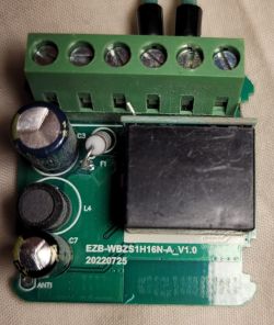
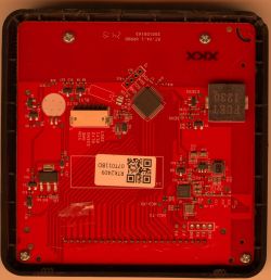
    Disassembled the device and found the following components:
    TM1621B - screen controller
    CMS32L051 - microcontroller that controls everything
    24C64 - EEPROM
    CB3S - (not pictured) - I assume it's a UART bridge between the CMS32L051 and the Wifi/TUYA server. CB3S connected to mainboard only /-/rx/tx

    My question is: can someone explain how the communication between the CB3S and the CMS works? I tried all the port speeds, but didn't see any meaningful information. I only see zeros, but the number of zeros can vary depending on load manipulation and button presses.

    Sincerely, xopek.
    Close-up of circuit board with capacitors, wires, and a yellow toroidal coil Close-up of a circuit board with electronic components and wired connections Green PCB with TM1621B and ISD1760 chips, labeled resistors and capacitors Electronic module with LCD screen and five control buttons Tuya Wi-Fi automatic circuit breaker with LCD display and control buttons.
  • ADVERTISEMENT
  • #2 21742115
    p.kaczmarek2
    Moderator Smart Home
    This is usually done via TuyaMCU.

    Protocol background:
    https://www.elektroda.com/rtvforum/topic3880546.html

    Analyzer tool:
    https://www.elektroda.com/rtvforum/topic3970199.html

    Setup guide:
    https://www.elektroda.com/rtvforum/topic4038151.html

    How do you probe that protocol? Do you know that connecting a main powered device to PC is very dangerous, the power supplies there are not isolated and there may be mains potential on UART lines? That being said, I also observed that you need to power whole device to get communication. Maybe try powering it from 24V DC on 230V input and see if it manages to start, but only if you understand what you're doing.

    Or skip packet capture , just do 2mb flash backup, flash obk, and try to go from there, but that may pose some other problems...
    Helpful post? Buy me a coffee.
  • ADVERTISEMENT
  • #3 21742186
    xopkep
    Level 4  
    >>21742115
    I'm aware of the danger. Thank you for your concern.
    Thanks for the links. I've read them. I think I searched the forum and googled them, but I couldn't find anything similar myself.
    Now I'll dump the data and flash the OBK.
    In the analysis log, I haven't seen anything about voltage, current, or status yet, but I think after switching to the OBK, it will become a little clearer and more convenient.
    A data table with columns ID, Type, VCnt, and Values containing varied entries
  • #4 21742261
    p.kaczmarek2
    Moderator Smart Home
    There is no separate dpID for current/voltage/etc. They are using compound format, raw bytes array, usually VCP, 2 bytes per voltage, scaled by 10, so precision to single decimal point.
    Search for: DP_TYPE_RAW_TAC2121C_VCP
    https://www.elektroda.com/rtvforum/find.php?q=DP_TYPE_RAW_TAC2121C_VCP
    On your capture, dpID 6 looks interesting. The first bytes are 091C, which can be decoded into 2332 decimal:
    Hexadecimal to decimal converter showing result 091C 2332
    The following is most likely your voltage value. Next bytes are 0, so I'd guess that they are current and power, just like in DP_TYPE_RAW_TAC2121C_VCP.
    Code: C / C++
    Log in, to see the code

    This format is known and works in OBK well. That being said, if you have some format that is not yet in OBK, then it's also not a problem - we're here to help, we can add a support for a new format for you.
    Helpful post? Buy me a coffee.
  • #5 21744091
    xopkep
    Level 4  
    Thanks for the reply. It was very interesting to read. Currently, my CB3S module refuses to respond to the flasher. I'll try a different UART adapter on Monday.
    One more small, theoretical question: will I be able to change the dpID value from OpenBeken? I'd like to be able to reset the total kWh counter.
  • #6 21744236
    p.kaczmarek2
    Moderator Smart Home
    You need to disconnect UART lines to flash.

    Total kWh reset is device-specific. It's recommended to capture packets and check how Tuya App does it first. Then you can easily mimic it from OpenBeken.
    Helpful post? Buy me a coffee.
  • #7 21744257
    xopkep
    Level 4  
    >>21744236
    The app doesn't do this at all; there's no such function.
    This is one of the reasons I tinkered with the device.
    I completely desoldered the CB3S module from the device to flash it.
  • ADVERTISEMENT
  • #8 21744820
    p.kaczmarek2
    Moderator Smart Home
    How do you connect CB3S to the UART converter? Posting a photo often can lead to quicker diagnosis and help.

    Well, maybe we can try to send dpID set to 0 from OBK and see if it's reset.
    Helpful post? Buy me a coffee.
  • #9 21745189
    xopkep
    Level 4  
    There are four pins between the mainboard and the CB3S: RX, TX, GND, VCC.
    I tried a different UART adapter (the first was a CH340, the second was a CP2102), but it still won't flash or read. I'll try using a programmer again; maybe it will work.
    CB3S module connected with wires to a PCB with electronic components
  • #10 21745200
    p.kaczmarek2
    Moderator Smart Home
    How do you power it, how long are the wires?
    Helpful post? Buy me a coffee.
  • ADVERTISEMENT
  • #11 21745246
    xopkep
    Level 4  
    The wires are no longer than 15 cm. I've tried powering the board from a UART adapter and an external 3 V power supply. I've encountered similar firmware issues before, and changing the UART adapter solved the problem.
  • #12 21750208
    xopkep
    Level 4  
    I'm out of ideas. I've already tried other adapters (CH340, CP2102, FTDI, and some other CHxxx). I've tried different power supply options. I can't connect to the module. However, the module works perfectly in the original device. All the adapters are working, and the power supply is fine. All that's left is to find a PC running WinXP, but the software for flash won't work there :(
  • #13 21750253
    divadiow
    Level 38  
    solder direct to RX/TX on the CB3S?
  • #14 21750280
    p.kaczmarek2
    Moderator Smart Home
    Is there anything on the other side of the board that CB3S is soldered on?
    Helpful post? Buy me a coffee.
  • #15 21751602
    xopkep
    Level 4  
    Yes, I direct-soldered to the RX/TX pins on the module. There's nothing on the back of the PCB, no mask, no traces.
  • #16 21757586
    xopkep
    Level 4  
    Wonderful! All my problems with this and the previous firmware were either Windows and driver-related! The port wouldn't work at speeds above 56,000! This is the first time I've seen this. I tried dozens of drivers and got the CH340G working, but the CP2102 still doesn't work.
    But in the end, I flashed the device, loaded TuyaMCU driver, and will continue to tinker to figure out how to receive data now.
    Sorry for bothering me :)
  • #17 21760320
    xopkep
    Level 4  
    Am I correct in understanding that in my case, I need to publish to MQTT something like this:
    Spoiler:

    //dpId 6, dataType 4-DP_TYPE_ENUM = set timer
    setChannelType 5 TextField
    linkTuyaMCUOutputToChannel 6 4 5
    //dpId 7, dataType 2-DP_TYPE_VALUE = timer remaining
    setChannelType 6 ReadOnly
    linkTuyaMCUOutputToChannel 7 2 6

    And then parse the data on the target device?
    Or is there a way to parse the data into the required components directly into OpenBeken and send the cleaned data?
    It's hard to understand the information in documentation in a foreign language, but I'm trying...

Topic summary

✨ The discussion focuses on the communication between the CB3S UART module and the CMS32L051 microcontroller within a Noname Automatic Reclosing Protector. The CB3S is presumed to act as a UART bridge connecting the CMS32L051 MCU to a WiFi/TUYA server. Attempts to decode the UART data at various baud rates resulted in streams of zeros, which vary with load changes and button presses. It is suggested that the communication protocol is based on TuyaMCU, a common protocol for IoT devices. Users are advised to power the device properly (e.g., 24V DC) to enable communication and to exercise caution due to mains voltage risks on UART lines. Analysis of captured data indicates the use of compound raw byte arrays for data transmission, specifically a format similar to DP_TYPE_RAW_TAC2121C_VCP, where voltage, current, and power values are encoded in 2-byte segments scaled by a factor of 10. The dpID 6 in the data stream likely corresponds to voltage and other electrical parameters, decoded from raw bytes. Flash dumping and firmware analysis (OBK flash) are recommended for deeper understanding and easier data interpretation.

FAQ

TL;DR: CB3S and CMS32L051 exchange TuyaMCU frames; metering often uses 2‑byte fields (voltage ÷10). “They are using compound format… scaled by 10.” [Elektroda, p.kaczmarek2, post #21742261]

Why it matters: This FAQ helps DIYers decode meters, flash CB3S, and map data to OpenBeken without bricking gear or misreading values.

Quick Facts

How does the CB3S talk to the CMS32L051 in this protector?

They use TuyaMCU over UART. Energy data often arrives as a compound RAW blob named TAC2121C_VCP: two bytes each for voltage, current, and power with scaling. “They are using compound format… scaled by 10.” OpenBeken already supports this mapping. [Elektroda, p.kaczmarek2, post #21742261]

What baud rate should I use to sniff the UART?

The thread does not fix a baud, but two points matter: power the whole device to see traffic, and treat the UART as potentially at mains potential. Use the shared analyzer tool workflow and keep isolation in mind while probing. [Elektroda, p.kaczmarek2, post #21742115]

What is TuyaMCU in simple terms?

TuyaMCU is the serial protocol that a Tuya Wi‑Fi module (CB3S) uses to exchange dpIDs with the product MCU. In this device, it carries metering and control frames between CB3S and CMS32L051. [Elektroda, p.kaczmarek2, post #21742115]

How do I decode voltage, current, and power from the RAW blob?

Use the TAC2121C_VCP layout: two bytes per value. Compute V = value/10, I = value/1000, P = value. For example, bytes 0x09 0x1C → 2332 → 233.2 V. Map these to OBK channels or first-of-type handlers. [Elektroda, p.kaczmarek2, post #21742261]

Which dpID carries the metering payload here?

In the posted capture, dpID 6 contains a RAW array whose first two bytes decode to 233.2 V after scaling. Current and power follow as adjacent two‑byte fields. [Elektroda, p.kaczmarek2, post #21742261]

Can I reset the total kWh counter from OpenBeken?

It’s device‑specific. First, capture how the Tuya app or MCU performs the reset, if available. Then send the same dpID command from OBK. Without a native function, you may try writing the dpID value (e.g., set to 0) carefully. [Elektroda, p.kaczmarek2, post #21744236]

My app has no kWh reset—any workaround?

Yes. Since the app lacks this function, capture UART when performing related actions, identify the dpID for energy total, and craft the matching OBK command. A member suggested testing a dpID write to 0 for reset. [Elektroda, p.kaczmarek2, post #21744257]

Is it safe to hook a PC UART to this mains device?

No, not directly. Power supplies may be non‑isolated, and mains potential can appear on UART lines. Power the entire device for traffic, and use isolation and safe practices. “Very dangerous” was emphasized in the thread. [Elektroda, p.kaczmarek2, post #21742115]

Why won’t my CB3S enter flashing mode even with multiple adapters?

Disconnect the module’s UART from the mainboard before flashing. Shared rails or active MCU lines can block the bootloader. This was a key fix suggested in the thread. [Elektroda, p.kaczmarek2, post #21744236]

What pins do I need to flash the CB3S?

Use four lines: RX, TX, GND, and VCC from the interconnect between the mainboard and the CB3S. The original poster confirmed these pins and attempted multiple adapters using them. [Elektroda, xopkep, post #21745189]

Do wire length and power source matter when flashing?

Yes. Keep leads short and ensure stable power. The OP used wires under 15 cm and tried both adapter power and an external 3 V supply while troubleshooting. [Elektroda, xopkep, post #21745246]

Should I solder directly to the CB3S pads?

Direct‑soldering to RX/TX on the CB3S is a valid troubleshooting step when headers or interposers fail. A community member recommended it in the thread. [Elektroda, divadiow, post #21750253]

Is there anything on the back of the CB3S carrier to check before flashing?

In this board, the back side had no mask or traces according to the OP. That reduces hidden pull‑ups or vias interfering with boot. Still confirm on your PCB revision. [Elektroda, xopkep, post #21751602]

What is OpenBeken and why use it here?

OpenBeken (OBK) is community firmware for Tuya modules. The maintainer suggested backing up the 2 MB flash, then flashing OBK to parse the metering blobs and expose MQTT control without the cloud. [Elektroda, p.kaczmarek2, post #21742115]

Does OpenBeken already support this VCP metering format?

Yes. OBK handles DP_TYPE_RAW_TAC2121C_VCP with per‑field scaling and channel mapping. This format is “known and works in OBK well,” per the maintainer. [Elektroda, p.kaczmarek2, post #21742261]

How do I get from stock firmware to OBK in three steps?

  1. Make a full 2 MB flash backup of the CB3S.
  2. Disconnect UART lines to the mainboard and power the module safely.
  3. Flash OBK, then map dpIDs and test metering decode. [Elektroda, p.kaczmarek2, post #21742115]
ADVERTISEMENT