logo elektroda
logo elektroda
X
logo elektroda
Dostępna jest polska wersja

Czy wolisz polską wersję strony elektroda?

Nie, dziękuję Przekieruj mnie tam

Configuring BK7231N Smart Plug with OpenBK7231T Firmware: LED & Power Metering Issues

vitya123 2577 17
ADVERTISEMENT
  • #1 21290161
    vitya123
    Level 6  
    Dear All,
    I just got a new smart plug which, obviously, I converted to this awesome firmware.
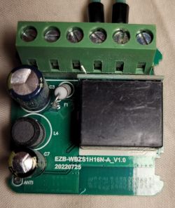
    The upgrade went smoothly. Now I need to configure it, and this is where I need some help: All the examples in the examples contain a (removable) module, but mine doesn't. It simply has a single board that has everything from the BK7231N chip, through the BL0937, to the relay, etc. on it. None of the example configs work.
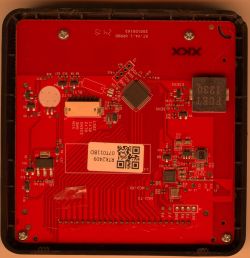
    By tracing the LEDs, the BL0937 lines (SEL, CF, CF1) I came to the conclusion that my module is connected like this:

    BK7231N pin - function
    15 - BL0937 SEL
    23 - BL0937 CF1
    22 - BL0937 CF
    16 - LED#1 (red)
    24 - LED#2 (blue)
    8 - relay

    However, when configuring the device with these settings, I have a number of problems:
    1. blue LED is always on, cannot change it.
    2. red LED follows the state of the relay, cannot set it on its own.
    3. there is no power metering AT ALL.
    4. the button gets detected, but it doesn't switch the relay on/off

    I wonder if there is a fundamental error I am overlooking... This is my config:

    {
      "vendor": "Tuya",
      "bDetailed": "0",
      "name": "Full Device Name Here",
      "model": "enter short model name here",
      "chip": "BK7231N",
      "board": "TODO",
      "flags": "1024",
      "keywords": [
        "TODO",
        "TODO",
        "TODO"
      ],
      "pins": {
        "8": "Rel;0",
        "15": "BL0937SEL;0",
        "16": "WifiLED_n;0",
        "22": "BL0937CF;0",
        "23": "BL0937CF1;0",
        "24": "LED_n;0",
        "26": "dInput_NoPullUp;0"
      },
      "command": "",
      "image": "https://obrazki.elektroda.pl/YOUR_IMAGE.jpg",
      "wiki": "https://www.elektroda.com/rtvforum/topic_YOUR_TOPIC.html"
    }


    Here are a couple of pics of my board:
    Close-up of a circuit board with an integrated circuit and electronic components. Close-up of a circuit board with a visible integrated circuit and electronic components.

    Once I figure this out I will post a full write up on it.
  • ADVERTISEMENT
  • #2 21290212
    divadiow
    Level 38  
    how did you flash it to OpenBeken? If you used UART did you take a backup of the factory firmware?
  • #3 21290219
    vitya123
    Level 6  
    >>21290212
    Yes, I flashed it using UART. And yes, I took a backup of the factory firmware. Although I have to say, I have never powered it on using the original firmware, I went straight for OB.
  • #4 21290223
    divadiow
    Level 38  
    what did Easy Flasher say about extracting the config from the backup?

    eg

    Screenshot of Easy Flasher software showing the extraction of configuration from a Tuya binary file.
  • #5 21290230
    vitya123
    Level 6  
    >>21290223
    Unfortunately this: "Failed to extract keys" :(

    I also tried to do it with the file downloaded from the web app - Download Tuya GPIO config from 0x1EE000, but got the same result - Failed to extract key.
  • ADVERTISEMENT
  • #6 21290231
    divadiow
    Level 38  
    I'd be happy to flash the backup to check boot logs if you're willing to share. sometimes the pin assignments are confirmable in the plan text output
  • ADVERTISEMENT
  • #7 21290259
    vitya123
    Level 6  
    yeah, sure, I'd be happy to share it. :) Sending you the link to it in a private message.
  • #8 21290260
    divadiow
    Level 38  
    just checking you've rebooted since config and you have the BL0937 driver running
    Screen showing active drivers with one BL0937 driver.
  • #10 21290265
    divadiow
    Level 38  
    vitya123 wrote:
    Hmmmm... what does this mean?

    on the main web gui it should have the drivers running listed
    Dashboard of the OpenBK_BK7231N_Fridge_Tuya_Plug displaying parameter summary.
  • #11 21290282
    vitya123
    Level 6  
    It says:
    0 drivers active, total 36
  • #12 21290286
    divadiow
    Level 38  
    boot log

    Code: Text
    Log in, to see the code


    area of interest:

    Code: Text
    Log in, to see the code


    which looks like your template might need to be
    Code: JSON
    Log in, to see the code


    are you sure there are two LEDs?
  • #13 21290324
    vitya123
    Level 6  
    Well, I tried your config (just to confirm: webapp - import, right?), but the situation hasn't improved...
    I can toggle the relay from the UI, but no sign of the power monitoring features:
    Screenshot of the OpenBK7231N user interface showing system information and a toggle option.

    About the LEDs: I have 2: a blue one, that seems to be always on, and a red one that comes on when the relay is on.
  • #14 21290333
    divadiow
    Level 38  
    >>21290324
    vitya123 wrote:
    just to confirm: webapp - import, right?

    yes. the BL0937 driver should start automatically on reboot with configured pins. if not, run "startdriver bl0937" in the startup command text or in an autoexec.bat

    Screenshot of the settings interface for the OpenBK_BK7231N_Fridge_Tuya_Plug device, where a startup command can be entered.
  • #15 21290335
    vitya123
    Level 6  
    I also notice a very weird thing now:
    When I press the button, the relay toggles just fine. However, when I'm in the webapp-GPIO finder, the button toggles ALL the GPIOs...
    GPIO Doctor Pins interface with a list of pins and buttons for setting outputs and inputs. Web interface of an application for managing GPIO with active Set Output Low settings and High status. Screenshot of GPIO Doctor Pins interface with buttons to set outputs high. Web app interface for managing GPIO outputs with visible buttons to set outputs to high.
  • #16 21290337
    divadiow
    Level 38  
    Code: JSON
    Log in, to see the code


    switch relay and button channels to 1 to change that behaviour
  • #17 21290360
    vitya123
    Level 6  
    Done and dusted - all working as I expect them to. Thank you for your help!!!!
  • ADVERTISEMENT

Topic summary

✨ The discussion revolves around configuring a smart plug utilizing the BK7231N chip with OpenBK7231T firmware. The user successfully flashed the firmware but encountered issues with LED behavior, power metering, and relay control. Despite following example configurations, the blue LED remained constantly on, the red LED only indicated relay status, and power monitoring features were non-functional. The community provided troubleshooting steps, including checking driver activation, rebooting, and adjusting GPIO settings. Ultimately, the user resolved the issues by modifying the relay and button channel configurations, leading to successful operation of the device.
Generated by the language model.

FAQ

TL;DR: “channal num is 1” — treat this plug as single‑channel, map BL0937 (CF=6, CF1=7, SEL=26), Relay=8, Btn=24, WifiLED_n=23, then start the BL0937 driver to restore metering and correct button behavior. [Elektroda, divadiow, post #21290286]

Why it matters: This FAQ helps DIYers flashing OpenBeken on BK7231N smart plugs fix no‑metering, LED, and button issues fast.

Quick Facts

What’s the working GPIO map for this BK7231N plug with BL0937?

Use: BL0937 CF=6, CF1=7, SEL=26; Relay=8; Button=24; WifiLED_n=23. Then reboot. This mapping came from the Tuya OEM config seen in the boot log and was confirmed in the final template that fixed the device. [Elektroda, divadiow, post #21290337]

How do I enable BL0937 power metering after flashing OpenBeken?

After setting pins, reboot and confirm the BL0937 driver appears under Drivers Running. If it does not, run startdriver bl0937 once, or add it to Startup commands or autoexec.bat for persistence. “Drivers running” is shown on the main GUI. [Elektroda, divadiow, post #21290333]

Why does pressing the button toggle every GPIO in GPIO Finder?

Relay and Button were on the default Channel 0, so the finder showed global toggling. Switch both to Channel 1 to isolate control. “Switch relay and button channels to 1 to change that behaviour.” [Elektroda, divadiow, post #21290337]

The web UI says “0 drivers active, total 36.” What does that mean?

It means no device drivers are currently active, so metering will not work yet. Configure pins and start the BL0937 driver, then reboot to load it automatically if added to Startup. [Elektroda, vitya123, post #21290282]

How do I apply the configuration via the OpenBeken WebApp?

  1. WebApp → Import the JSON template with the pin map.
  2. Reboot; verify BL0937 is listed under Drivers Running.
  3. If missing, add startdriver bl0937 to Startup or autoexec.bat and reboot. This ensures power metering is initialized on every boot. [Elektroda, divadiow, post #21290333]

Can Easy Flasher extract the Tuya GPIO config from backup?

Sometimes not. Users can see “Failed to extract keys” when attempting to pull Tuya GPIO config from 0x1EE000. If that happens, you need an alternative, like reading the OEM boot log, to recover pins. [Elektroda, vitya123, post #21290230]

How can I recover the GPIO map when key extraction fails?

Capture and read the Tuya boot log. Look for oem cfg fields such as rl1_pin:8, bt1_pin:24, netled1_pin:23, ele_pin:6, vi_pin:7, sel_pin:26. Mirror those values in OpenBeken pin roles for Relay, Button, WifiLED_n, and BL0937. [Elektroda, divadiow, post #21290286]

This plug uses a single board, not a plug‑in module—does that change setup?

No. You still configure OpenBeken by mapping pins to roles and starting the BL0937 driver. Examples with removable modules may not fit; rely on your board’s traces or the OEM boot log to map pins. [Elektroda, vitya123, post #21290161]

Should I back up the factory firmware before flashing OpenBeken?

Yes. Flash over UART and make a full backup first. The user in this thread backed up their factory image before applying OpenBeken, which enabled later analysis and recovery options if needed. [Elektroda, vitya123, post #21290219]

How many controllable channels does this smart plug expose?

The OEM boot log prints “channal num is 1,” so this design exposes one relay channel. Configure Relay and Button on the same channel (e.g., Channel 1) for predictable control. [Elektroda, divadiow, post #21290286]

How should I configure the LEDs?

Set WifiLED_n to GPIO 23 for network status. The unit also has a blue LED that stays on and a red LED tied to the relay, as observed by the user. Only the net LED was explicitly configured in the working template. [Elektroda, vitya123, post #21290324]

How do I confirm everything is fixed?

You should toggle the relay from the UI and button without unintended GPIO changes, and power metering should read values. The reporter closed with “Done and dusted – all working as I expect them to.” [Elektroda, vitya123, post #21290360]
Generated by the language model.
ADVERTISEMENT