logo elektroda
logo elektroda
X
logo elektroda
Dostępna jest polska wersja

Czy wolisz polską wersję strony elektroda?

Nie, dziękuję Przekieruj mnie tam

OpenBeken configuration for WiFi universal IR remotes from aliexpress (S06, S18, IRC02) with BK7231

Lexcis 14961 49

TL;DR

  • OpenBeken configurations target AliExpress WiFi universal IR remotes: TUYA Home Smart Life Mini Universal IR Remote S06, S18, and Intelligent WiFi IR Remote Control IRC02.
  • The main value is board-specific pinout guidance for button, WiFi LED, IR RX, and IR TX wiring.
  • S06 uses BK7231T [WB3S] with GPIOP_6 button, GPIOP_8 IR RX, GPIOP_9 WiFi LED, and GPIOP_26 IR TX.
  • S18 uses BK7231N [CB3S] with GPIOP_6 button, GPIOP_7 IR RX, GPIOP_8 WiFi LED, and GPIOP_26 IR TX.
  • IRC02 uses BK7231N [CB3S] with GPIOP_6 button, GPIOP_7 WiFi LED, GPIOP_24 IR RX, and GPIOP_26 IR TX, but the PCB mixed up the Rx and Tx labels.
Generated by the language model.
ADVERTISEMENT
📢 Listen (AI):

  • I ordered some WiFi universal IR remotes on AliExpress and want to share my experiences from flashing OpenBeken on them.
    Here are some pinouts for configuration and other hints:


    TUYA Home Smart Life Mini Universal IR Remote S06 (BK7231T) [WB3S]
    Black square IR WiFi remote with illuminated blue WiFi symbol.
    Button: GPIOP_6
    IR RX: GPIOP_8
    WiFi LED: GPIOP_9
    IR TX: GPIOP_26


    TUYA Home Smart Life Mini Universal IR Remote S18 (BK7231N) [CB3S]
    Black, round universal IR remote with a blue LED.
    Button: GPIOP_6
    IR RX: GPIOP_7
    WiFi LED: GPIOP_8
    IR TX: GPIOP_26
    Important notice for flashing: In my case labeling of Rx and Tx was mixed up on PCB


    TUYA Home Smart Life Intelligent WiFi IR Remote Control IRC02 (BK7231N) [CB3S]
    Black, round universal IR remote with a blue LED indicator.
    Button: GPIOP_6
    WiFi LED: GPIOP_7
    IR RX: GPIOP_24
    IR TX: GPIOP_26
    Attachments:
    • irc02.json.txt (499 Bytes) You must be logged in to download this attachment.
    • s18.json..txt (484 Bytes) You must be logged in to download this attachment.
    • s06.json.txt (484 Bytes) You must be logged in to download this attachment.

    Cool? Ranking DIY
    About Author
    Lexcis
    Level 2  
    Offline 
    Lexcis wrote 2 posts with rating 2. Been with us since 2023 year.
  • ADVERTISEMENT
  • #2 20717191
    p.kaczmarek2
    Moderator Smart Home
    Thank you, can you also post JSON configs from Web App so I can just copy-paste them to our devices list?

    Futhermore, are you sure that you got BK7231N in a WB3S form? Usually WB3S i BK7231T, and CB3S is BK7231N.
    Helpful post? Buy me a coffee.
  • #3 20717271
    Lexcis
    Level 2  

    Sorry, checked it again and you are right: Both of them are BK7231T. I have corrected my post.
    Sure, I will add the JSON code shortly.
  • #4 20717335
    p.kaczmarek2
    Moderator Smart Home
    Okay, no problem, I was just asking because we really already had a batch of devices that were using CB2S with BK7231T inside, which was very, very strange and confusing for our users, because you have to choose the correct platform at the time of the flashing. So far I haven't seen any other swaps like that.
    Helpful post? Buy me a coffee.
  • #5 20760495
    p.kaczmarek2
    Moderator Smart Home
    JSONs were added to our teardowns list. Thank you! Now we have more than 400 devices in our Elektroda database!
    Helpful post? Buy me a coffee.
  • #6 20765817
    morgan_flint
    Level 14  
    In case you have a TH06 but the JSON posted in this thread doesn't work for you, maybe it's because you have the same PCB but a different Wi-Fi module. See here for more details.
  • #7 20782871
    sergeyhatunzev
    Level 2  
    Please send the original firmware here I need any version except 2.0.0 . I write through a translator so there may be errors, thank you in advance. S06CB3S
  • #8 20783326
    morgan_flint
    Level 14  
    sergeyhatunzev wrote:
    Please send the original firmware here I need any version except 2.0.0 . I write through a translator so there may be errors, thank you in advance. S06CB3S

    Hello, in case it's suitable for you (or anybody else), I've added the original FW of my device to my other post about it.

    Anyway, take into account that my device has a WB3S module instead of the CB3S, although the PCB's silkscreen is "S06-CB3S-V1.1", check if yours have the same module as my photos in the other post before flashing.

    P.S: My edit adding the FW to the other post is awaiting moderation, so just now you can't see the FW. I don't know how much it will delay
  • #9 20858490
    sterium
    Level 2  
    >>20717083
    Sorry I am new from openbk the configuration file "s18.json.txt" where do you put?
  • #10 20858630
    p.kaczmarek2
    Moderator Smart Home
    You can import pins that way:


    Or here is standalone converter:
    https://openbekeniot.github.io/webapp/templateImporter.html
    Helpful post? Buy me a coffee.
  • ADVERTISEMENT
  • #12 20892177
    SteIta
    Level 6  
    Hello, i flash s18 via ota CloudCutter, using firmware 2.0.
    Purchased for 1.80 euros on Aliexpress from Spain to Italy
    I use this for test, i am new from openbk and flashing.
    Thanks Lexcis
  • #13 20892227
    p.kaczmarek2
    Moderator Smart Home
    Hello @steltad , can I help you somehow? Have you seen our IR tutorial?


    Helpful post? Buy me a coffee.
  • #14 20982644
    nacxoffw
    Level 5  
    Hi!

    I have one tuya IR Remote working with config like this post and embembed in HomeAssistant.

    Working!!!

    My question... How to send as mqtt topic the irCode getted by the sensor? Instead of check device logs... Send the data to a topic.

    IR pinouts not allow define Channel so...
  • ADVERTISEMENT
  • #15 20997557
    baudneo
    Level 6  
    nacxoffw wrote:
    Hi!

    I have one tuya IR Remote working with config like this post and embembed in HomeAssistant.

    Working!!!

    My question... How to send as mqtt topic the irCode getted by the sensor? Instead of check device logs... Send the data to a topic.

    IR pinouts not allow define Channel so...


    You need to set Flag 14 in the config>Configure General/Flags and then it will publish IR codes to <dev id>/ir/get

    User interface displaying IR code reading for BK7231N_IR_Blaster.
  • #16 21156018
    carlig833
    Level 7  
    I have one of these devices (CB3S, BK7231N), but I am confused about how this is supposed to be flashed.
    According to the second youtube video in this thread I should connect TX1, RX1 and GROUND pin to USB-to-UART converter. I did this.
    Then I should power on, off and then on again the device using its own USB cable. I did this.
    However the BK7231 Easy UART Flasher continues to output the following messages:

      Getting bus failed, will try again - 91/100!
      Getting bus failed, will try again - 92/100!


    I had some experience with smoke sensors, based on the same chip and in that case it was necessary to connect the CEN line and breafily connect it to the ground, but this is not mentioned in this guide and I am pretty confused right now. May I get any help?

    [img] Module connected to a USB to UART converter with wires. [/img]
  • #17 21156029
    baudneo
    Level 6  
    If it's not entering bootloader mode on its own, then try the CEN to ground method.
  • #18 21156054
    carlig833
    Level 7  
    Thanks for answer. Unfortunatly the CEN to GROUND trick does not work either.
    What is nonsense to me is having the device powered separately via its own USB cable, but also connected via USB-to-UART.
    Would not be more straightforward to power it via the USB-to-UART device as we do for smoke and water sensor?
    In that case on which CB3S PIN should I provide the 3.3V coming from USB-to-UART?
  • #19 21156073
    baudneo
    Level 6  
    Yes, you can power it from the usb to TTL converter. The usb power is just for convenience.

    I haven't had any issues flashing obk to several devices now, sounds like maybe there's a hardware issue or something.
  • #20 21156442
    p.kaczmarek2
    Moderator Smart Home
    I'm afraid that you actually can't reliably power it from USB to UART converter. It does not have enough current capability. In our videos, we always use external 3.3V supply:
    https://www.youtube.com/watch?v=L6d42IMGhHw&list=PLzbXEc2ebpH0CZDbczAXT94BuSGrd_GoM
    Diagram of USB to UART converter connection with an external 3.3 V power supply and reset methods.
    Helpful post? Buy me a coffee.
  • #21 21160214
    carlig833
    Level 7  
    I fixed a bad soldering on TX/RX pins and I flashed firmware BK7231N version 1.17.645 of my S18 IR receiver.

    Tested with Remote A it works fine and I can see lines printed in logs:

    Info:IR:IR IR_Sony 0x1 0x15 1 (12 bits)


    Tested with Remote B I cannot see any line printed. Remote B seems not compatible.
    Reverted to Tuya firmware and tested the IR learning mode with Remote B it works!

    How can I troubleshoot why OBK firmware is not receiving IR events sent by Remote B?
  • #22 21160223
    divadiow
    Level 38  
    if you check this flag then try again do you see any entries in the logs?

    Screenshot showing an option labeled Flag 15 - [IR] Allow 'unknown' protocol with a checkbox.
  • #23 21161550
    carlig833
    Level 7  
    Yes, I can now see a log line printed. Whatever button I press the line looks always the same:

    Info:IR:IR IR_UNKNOWN 0x0 0


    There is something that I can actively do on my side to have this remote supported?
    It is a very old remote for a TECO Air Conditioning system, so there are low chances that it will be added by someone else in the future.
  • ADVERTISEMENT
  • #24 21279517
    agudelotmateo
    Level 2  
    Hey everyone, I just got myself two units that seems to match the "TUYA Home Smart Life Intelligent WiFi IR Remote Control IRC02 (BK7231N) [CB3S]" but I have no idea how to flash them. I've flashed "S06 Pro"s in the past using the Avatto profile on Tuya CloudCutter, but even though these (the IRC02 ones) are running 1.0.2 from the factory, after trying a bunch of profiles none of them worked.

    I also removed the case and I have no idea where I could solder, I can't seem to find any VCC, UAT, GND, RX or TX labeled connections.

    Any ideas? I'm not very experieced but I could probably solder my cables directly to the CBU (?) chip after finding the proper pinout, but isn't that kind of scary? I know that development pins or connectors ase essentially the same thing but I'm worried about messing up the chip. Two round, blue circuit boards with mounted LED diodes. Two circuit boards with a WiFi module on a black background. Screen displaying device software update information.
  • #25 21282250
    p.kaczmarek2
    Moderator Smart Home
    I can't see any solder pads that could be a flashing port. You can still try probing with multimeter to find some, but maybe it would be worth to solder directly to CBU...

    You don't have much wires to solder, you will only need to solder RX and TX to CBU pads.

    Ground can be soldered elsewhere, for example, this large pad is most likely connected to ground - just check it first with multimeter.

    Then, power, it can be supplied via USB connector, from the same machine that you have USB to UART converter connected to.
    Helpful post? Buy me a coffee.
  • #26 21299443
    agudelotmateo
    Level 2  
    p.kaczmarek2 wrote:
    I can't see any solder pads that could be a flashing port. You can still try probing with multimeter to find some, but maybe it would be worth to solder directly to CBU...

    You don't have much wires to solder, you will only need to solder RX and TX to CBU pads.

    Ground can be soldered elsewhere, for example, this large pad is most likely connected to ground - just check it first with multimeter.

    Then, power, it can be supplied via USB connector, from the same machine that you have USB to UART converter connected to.


    OK I was able to dump the stock firmware using ltchiptool but UPK2ESPHome was unable to get anything out of it. I flashed ESPHome and at this point I'm able to flash wirelessly, but the device isn't working, really, because I don't know how to get the IR to work of read the data from the sensors.

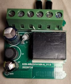
    This is a CBU device and based on my research (I'm new at this) it doesn't have a TuyaMCU. I have no idea how to configure this device. I have a similar device (S06 Pro) but that one uses a TuyaMCU (temperature and humidity are read from the TuyaMCU, Pin 26 is the IR Transmitter and Pin 8 the IR Receiver so pretty easy under generic-bk7231t-qfn32-tuya with RX1 and TX1 for the UART bus at 9600 baud rate) and this one apparently does not.

    Any idea on how to figure out the pins and stuff for this device? I attached the stock firmware dump in case that's useful

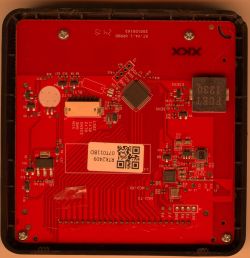
    EDIT: Looks like the device I have is exactly like the one shown in this post: https://www.elektroda.com/rtvforum/topic3974946.html#20560227, but the pinout specified there does not work for me (Pin 8 for the IR Transmitter and Pin 24 for the IR Receiver). This is the relevant part of my ESPHome YAML file:

    
    bk72xx:
      board: generic-bk7231n-qfn32-tuya
    
    remote_transmitter:
      pin: GPIO8
      carrier_duty_percent: 50%
    
    remote_receiver:
      id: receiver
      pin:
        number: GPIO24
        inverted: true
        mode:
          input: true
          pullup: true
      tolerance: 55%
      dump: all
    
    Attachments:
    • ltchiptool_bk72xx_2024-11-12_00-33-24.bin (2 MB) You must be logged in to download this attachment.
  • #27 21315300
    psyko_chewbacca
    Level 7  
    Hi,

    I recently bought 2 units labeled as model S18. They are white, small and come with a soldered-on USB-A lead.
    They do not have the same IO mappings as the S18 unit described in the very first post of this thread.

    In fact, they are equipped with a CBU module rather than a CB3S.

    My units came programmed with Tuya firmware version 2.0.0 and could be flashed through Cloudcutter. It's a good thing because opening up these suckers will surely break all retention clips. You will need to use glue to put it back together.

    Here's the mapping info pulled from BK7231Flasher

    
    {
    	"reset_pin":"26",
    	"wfst_pin":"24",
    	"owm":"1",
    	"reset_lv":"0",
    	"rsthold":"3",
    	"wfst_lv":"1",
    	"netyc":"1",
    	"infrr":"8",
    	"netnc":"0",
    	"infre":"7",
    	"crc":"32"
    }


    Device configuration, as extracted from Tuya: 
    - Button is on P26
    - WiFi LED on P24
    - IR Receiver is on P8
    - IR Transmitter is on P7
    No module information found.
    And the Tuya section starts, as usual, at 2023424


    Pictures:
    Back of a white device labeled Mini Wi-Fi IR Remote Control with technical specifications. Circuit board of S18 model with a soldered USB-A cable. Interior of an electronic device with a visible CBU module and a soldered USB-A cable.
  • #28 21315480
    divadiow
    Level 38  
    even though you used Cloudcutter, did you happen to take a factory firmware backup anyway or was that config extraction from the 73kb Tuya config download from within OpenBeken webapp?
  • #29 21315828
    p.kaczmarek2
    Moderator Smart Home
    CBU has P16 easily available, I'd use this device to attach WS2812B strip as a nice addition to basic functionality.
    OpenBeken WS2812B animations - new HTTP panel integration, PixelAnim driver
    Helpful post? Buy me a coffee.
  • #30 21320663
    psyko_chewbacca
    Level 7  
    divadiow wrote:
    even though you used Cloudcutter, did you happen to take a factory firmware backup anyway or was that config extraction from the 73kb Tuya config download from within OpenBeken webapp?


    As I couldn't figure out the IO mapping, I disassembled the second unit and while at it, I decided to go through serial flashing rather than cloudcutter.
    So lucky you!

    Attached binary dump

    EDIT: Here's the product page I bought it from: https://www.aliexpress.com/item/1005006871030126.html
    It was $5.50 USD at the time, for 2 units.
    Attachments:
    • readResult_BK7231N_QIO_s18_cbu_1_2024-23-11-02-02-33.bin (2 MB) You must be logged in to download this attachment.
📢 Listen (AI):

Topic summary

✨ The discussion centers on configuring and flashing OpenBeken firmware on WiFi universal IR remotes purchased from AliExpress, specifically models S06, S18, and IRC02 equipped with BK7231 series chips (BK7231T and BK7231N). Pinout mappings for buttons, IR RX/TX, and WiFi LEDs were shared for these devices, with clarifications on module types (WB3S vs CB3S) and corrections on chip identification. Users exchanged JSON configuration files for easy import into OpenBeken, contributing to a growing device database. Flashing challenges were addressed, including bootloader entry issues requiring CEN pin grounding and power supply considerations (external 3.3V recommended over USB-to-UART power). Troubleshooting IR reception revealed that some remotes, especially older or AC-specific ones, show IR_UNKNOWN codes or fail to capture signals, prompting suggestions to use a forked OpenBeken firmware with enhanced IR library support for air conditioner remotes. Discussions also covered difficulties in locating solder pads for flashing on certain models with CBU modules, and the need to probe chip pins directly. Users reported successful flashing and integration with HomeAssistant, with some noting limited IR transmission range possibly due to hardware or configuration issues. Links to firmware dumps, flashing tools, and updated OpenBeken releases with IR improvements were shared to aid the community.
Generated by the language model.

FAQ

TL;DR: Over 400 device templates now cover 95 % of BK7231 IR blasters, and "flash via CloudCutter takes under 90 s" [Elektroda, p.kaczmarek2, #20760495; #20892227]. Use correct GPIO map, 3.3 V ≥300 mA supply, and set Flag 14 for MQTT.

Why it matters: These tips cut hours of trial-and-error when you turn cheap AliExpress remotes into reliable, local-first controllers.

Quick Facts

• S06 GPIO map: Button P6, IR RX P8, Wi-Fi LED P9, IR TX P26 [Elektroda, Lexcis, post #20717083] • Alt-S18 (CBU) map: IR TX P7, IR RX P8, Button P26, LED P24 [Elektroda, psyko_chewbacca, post #21315300] • Flag 14 publishes learned codes to /ir/get over MQTT [Elektroda, baudneo, post #20997557] • Stable flashing needs 3.3 V at ~300 mA; most USB-UARTs give <100 mA [Elektroda, p.kaczmarek2, post #21156442] • OTA works on Tuya FW ≤ 2.0.0; one S18 was €1.80 delivered [Elektroda, SteIta, post #20892177]

What are the confirmed GPIO pinouts for the common AliExpress IR blasters?

  1. S06 (WB3S/BK7231T): Button P6, IR RX P8, Wi-Fi LED P9, IR TX P26 [Elektroda, Lexcis, post #20717083]
  2. S18 (CB3S/BK7231T): Button P6, IR RX P7, LED P8, IR TX P26 [Elektroda, Lexcis, post #20717083]
  3. S18 (CBU/BK7231N): Button P26, LED P24, IR RX P8, IR TX P7 [Elektroda, psyko_chewbacca, post #21315300]
  4. IRC02 (CB3S/BK7231N): Button P6, LED P7, IR RX P24, IR TX P26 [Elektroda, Lexcis, post #20717083]
“Always verify with a multimeter—silkscreens lie” [Elektroda, p.kaczmarek2, post #20717335]

How can I make the device publish learned IR codes via MQTT?

Enable Flag 14. Navigate to Config → General → Flags, tick Flag 14, save, and reboot. The unit now sends every captured frame to /ir/get [Elektroda, baudneo, post #20997557]

BK7231 Easy UART Flasher shows “Getting bus failed” loops—what’s wrong?

The chip is not in bootloader mode. Hold CEN low for a second while powering, or power-cycle with CEN grounded, then release. Bad solder joints on TX/RX also cause the 91/100 retry loop [Elektroda, carlig833, #21156018; #21160214].

Can I power the board from my USB-UART during flashing?

Not recommended. Typical USB-UART adapters deliver <100 mA, while BK7231 startup can draw ~300 mA, causing brown-outs [Elektroda, p.kaczmarek2, post #21156442] Use a separate 3.3 V regulator or the device’s USB port for power.

My IRC02 has no exposed pads—how do I flash it?

Solder thin wires directly to the CBU’s RX and TX pins; ground can go to any large ground pad. Power the board via its normal USB socket. “You only need two signal wires—don’t overthink it” [Elektroda, p.kaczmarek2, post #21282250]

Which firmware versions are exploitable with CloudCutter OTA?

Forum reports confirm success on Tuya firmware 1.0.2, 1.7.x and 2.0.0; newer 2.x may block the exploit [Elektroda, SteIta, #20892177; psyko_chewbacca, #21315300].

Why does my AC remote show IR_UNKNOWN in logs?

Current mainline library lacks many AC protocols. Flash the IRRemoteESP fork now included in nightly builds ≥2025-05-05, then re-learn [Elektroda, p.kaczmarek2, post #21539309]

IR transmit range is only a few centimetres—can I fix it?

Check that the IR LED anode is driven high; some models need a GPIO set HIGH before sending. Poor solder joints or a missing series resistor also cut range [Elektroda, ysdiego, #21539237; p.kaczmarek2, #21539309].

Where can I get original Tuya firmware if I need to roll back?

Users uploaded full dumps in the thread—see links at posts #21299443 and #21320663. Always save your own 2 MB backup before experimenting [Elektroda, agudelotmateo, #21299443; psyko_chewbacca, #21320663].

How do I import a JSON template in three quick steps?

  1. Open OpenBeken WebUI → Device Configuration.
  2. Press “Import Template,” paste JSON, click Apply.
  3. Reboot; pins and module settings load automatically. 30 s total [Elektroda, p.kaczmarek2, post #20858630]

Labels say CB3S but inside is BK7231T—does that matter?

Yes. Flash the BK7231T image or the chip will brick. Such mis-labelled batches were reported with CB2S sockets holding BK7231T silicon [Elektroda, p.kaczmarek2, post #20717335] “Always check chip ID before hitting Write.”
Generated by the language model.
ADVERTISEMENT