Your suggestion did help me, but it works differently for me. Steps I did:
1. wire TX, RX and GND
2. connect USB/UART to computer
3. start (windows) BK7231 UART flasher
4. connect switch to USB for power
5. shortly wire GND to pin 1 (RST)
6. disconnect GND
The results are as below
note to me: don't swap TX and RX, because that leads to frying a SMD
Unfortunately, I don't see it come up as an AP neither can I find it on my network when I add wifi credentials. Any flag box I should tick?
{
"rl1_lv":"1",
"on_off_cnt":"10",
"onoff_rst_m":"0",
"led1_pin":"9",
"onoff_clear_t":"6",
"rand_dpid":"42",
"net_trig":"4",
"netled1_lv":"0",
"jv":"100",
"onoff_rst_type":"2",
"total_bt_pin":"6",
"nety_led":"0",
"total_stat":"0",
"reset_t":"5",
"netled1_pin":"8",
"remote_add_dp":"49",
"remote_list_dp":"50",
"net_type":"0",
"inch_dp":"44",
"rf_width":"345",
"module":"CB3S",
"ch_cddpid1":"9",
"remote_io":"26",
"onoff1":"14",
"init_conf":"38",
"led1_lv":"0",
"zero_select":"0",
"onoff_type":"0",
"series_ctrl":"0",
"total_bt_lv":"0",
"cyc_dpid":"43",
"remote_select":"1",
"ch_num":"1",
"rl1_pin":"24",
"netn_led":"0",
"ch_dpid1":"1",
"crc":"16"
}
Device configuration, as extracted from Tuya:
- LED (channel 1) on P9
- Pair/Toggle All Button on P6
- WiFi LED on P8
- TglChannelToggle (channel 1) on P14
- Relay (channel 1) on P24
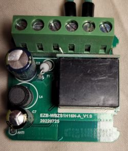
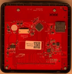
Device seems to be using CB3S module, which is using BK7231N.
And the Tuya section starts, as usual, at 2023424

![[BK7231N/CB3S] Mhcozy TYWRA-RF Relay Module (Dry Contact) Configuration & Setup Guide](https://obrazki.elektroda.pl/1802123700_1685975320_thumb.jpg "[BK7231N/CB3S] Mhcozy TYWRA-RF Relay Module (Dry Contact) Configuration & Setup Guide")
![[BK7231N/CB3S] Mhcozy TYWRA-RF Relay Module (Dry Contact) Configuration & Setup Guide](https://obrazki.elektroda.pl/1802123700_1685975320.jpg "[BK7231N/CB3S] Mhcozy TYWRA-RF Relay Module (Dry Contact) Configuration & Setup Guide")