logo elektroda
logo elektroda
X
logo elektroda
Dostępna jest polska wersja

Czy wolisz polską wersję strony elektroda?

Nie, dziękuję Przekieruj mnie tam

[Solved] Rewriting Firmware for Wi-Fi DIY Smart Switch (2022.10.15 model) using CB2S (BK7231N)

hga00453 5589 11
ADVERTISEMENT
  • #1 20396816
    hga00453
    Level 3  
    Hello everyone.
    This is my first post on this site. I'm a newbie, please help me out.

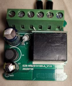
    Now, I have the following Smart Switch at hand and am trying to rewrite the firmware for the model with [2022.10.15] written on the printed circuit board.
    Rewriting Firmware for Wi-Fi DIY Smart Switch (2022.10.15 model) using CB2S (BK7231N)
    Rewriting Firmware for Wi-Fi DIY Smart Switch (2022.10.15 model) using CB2S (BK7231N)
    Rewriting Firmware for Wi-Fi DIY Smart Switch (2022.10.15 model) using CB2S (BK7231N)
    Rewriting Firmware for Wi-Fi DIY Smart Switch (2022.10.15 model) using CB2S (BK7231N)

    In past posts of this site, I found the post;
    https://www.elektroda.com/rtvforum/topic3895572.html
    may be helpful, but so far I have been unable to rewrite the firmware.

    I have gathered a lot of information and the Wi-Fi module used in this device is CB2S (BK7231N), which matches the information in the datasheet, so I hope to be able to rewrite that.
    I have tried to flash the firmware but I can not enter to the flash mode.

    So far, I have attempted the following,
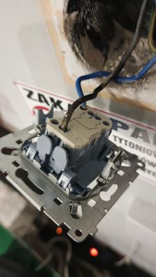
    (1) Supply 5VDC to AMS1117 as external power supply
    (2) Connect RX1 and TX1 of CB2S to TX and RX of USB to UART converter by cross connection
    (3) Cut the pattern on the board for connecting RX1 to Button.
    (4) Rewrite with BK7231 GUI Flash Tool 1.0.4

    Does anyone have specific information on rewriting the firmware for this model?

    Added after 23 [minutes]:

    Add supplemental information.
    The following figure shows actual pictures of (1) external power supply and (3) pattern cutting on the board.
    Please feel free to point out any mistakes.
    Rewriting Firmware for Wi-Fi DIY Smart Switch (2022.10.15 model) using CB2S (BK7231N)
  • ADVERTISEMENT
  • Helpful post
    #2 20396890
    p.kaczmarek2
    Moderator Smart Home
    Hello, I would like to suggest you the most reliable approach.
    Just desolder CB2S.
    First add some flux to the pads and remove solder with soldering wick:
    Desoldering process on a green circuit board using a soldering iron and solder wick.
    Then solder the wires:
    Close-up of an electronic module with visible pads and pin labels.
    Then power module from 3.3V and connect to USB to TTL:
    Rewriting Firmware for Wi-Fi DIY Smart Switch (2022.10.15 model) using CB2S (BK7231N)
    Then use BK GUI flasher. If it doesn't work for you (there are some rare reports that BK GUI doesn't work with certain USB converters, but hid_download_py does), use hid_download_py method from this video:


    Make sure that OBK access point shows up.
    Then desolder wires, and clear the module pads:
    Electronic module with soldered wires and a holding clamp.
    Then prepare to solder back the module, add some flux to the pads:
    Desoldering braid over a circuit board with electronic components.
    And solder back the module:
    Soldering a component onto a printed circuit board using a soldering iron.
    Helpful post? Buy me a coffee.
  • #3 20396918
    hga00453
    Level 3  
    Hi, p.kaczmarek2
    Thank you for your reply.
    The information you provided is in the video and is very clear.

    It seems that the most common method is to disconnect the Wi-Fi sub-board from the main board (unsolder it) and rewrite it on its own.
    If this seems to be the only way, I will try it.

    Does anyone have any information on how to rewrite this model (2022.10.15) without removing the sub board?
  • ADVERTISEMENT
  • Helpful post
    #4 20396936
    p.kaczmarek2
    Moderator Smart Home
    hga00453 wrote:

    Does anyone have any information on how to rewrite this model (2022.10.15) without removing the sub board?

    1. Locate AMS1117 3.3V LDO regulator on the board
    2. connect 5V to AMS1117 input, connect common ground
    3. connect RX and Tx, also make sure that RX and TX is not used for something else on the board (if so, cut the trace)
    4. Start flashing in the programmer tool. Try BK GUI flasher, if it fails, you can also try hid_download_py
    5. The tool will wait for device reboot (for "getting bus"), then:
    OPTION A: disconnected 5V power supply and reconnect it quickly (so module reboots)
    OPTION B: use extra CEN wire and short it for 0.25 seconds to ground (so module reboots)
    6. flashing should proceed

    hid_download_py commands for firmware backup (2MB, please do it first!) and writing are on the video linked above.

    This method should work as long as you have no interference on RX/TX lines.
    You can also read this topic (I also cut the trace here):
    ZN268131 WiFi Smart Switch that allows you to connect a bistable button
    You can also watch this CB2S flashing video (I had to cut the trace there):


    Rewriting Firmware for Wi-Fi DIY Smart Switch (2022.10.15 model) using CB2S (BK7231N)
    Rewriting Firmware for Wi-Fi DIY Smart Switch (2022.10.15 model) using CB2S (BK7231N)
    Helpful post? Buy me a coffee.
  • ADVERTISEMENT
  • #5 20397307
    hga00453
    Level 3  
    Hi, @p.kaczmarek2
    Thank you for your additional information provided.
    I have tried them in the past, but failed to flash the firmware.

    It seems that the RX and TX pins are connected to the relay module, as the relay ticks when I run the flashing application.
    It seems like there is a missing pattern cut on the board, so I guess I should still follow your advice and separate the CB2S sub-board of the Wi-Fi module before flashing.
  • Helpful post
    #6 20397465
    p.kaczmarek2
    Moderator Smart Home
    There are many things that can go wrong with flashing BK7231. It is not guaranteed that desoldering WiFi module will help, but at least it will tell you that your problem is not the RX/TX tracks interference.
    Helpful post? Buy me a coffee.
  • ADVERTISEMENT
  • #7 20397597
    hga00453
    Level 3  
    Hi, @p. kaczmarek2
    Your advice has been very helpful.
    The direction you recommended is still generic for the future, so I will try that approach.
    Thanks.
  • #8 20398512
    hga00453
    Level 3  
    As suggested, I responded by separating the CB2S sub-board from the main board.
  • #10 20405966
    hga00453
    Level 3  
    p.kaczmarek2 wrote:
    Is the flashing working now? @hga00453

    YES! I did it.
    Rewriting Firmware for Wi-Fi DIY Smart Switch (2022.10.15 model) using CB2S (BK7231N)
    Rewriting Firmware for Wi-Fi DIY Smart Switch (2022.10.15 model) using CB2S (BK7231N)
  • #11 20405974
    hga00453
    Level 3  
    Just remove the WiFi (CB2S) module from the main board.
  • #12 20405987
    p.kaczmarek2
    Moderator Smart Home
    Very good job, it's' the most reliable way.
    Helpful post? Buy me a coffee.

Topic summary

✨ A user seeks assistance in rewriting the firmware for a Wi-Fi DIY Smart Switch (model 2022.10.15) utilizing the CB2S (BK7231N) module. Initial attempts to flash the firmware were unsuccessful, primarily due to difficulties entering flash mode and potential interference from RX/TX connections to the relay module. Community members suggest desoldering the CB2S module from the main board to eliminate interference issues. Detailed steps are provided, including connecting power to the AMS1117 regulator, using BK GUI flasher or hid_download_py for flashing, and ensuring proper connections. After following the advice and separating the CB2S module, the user successfully flashed the firmware.
Generated by the language model.

FAQ

TL;DR: For CB2S (BK7231N) smart switches, power at 3.3V and follow the "most reliable approach": desolder CB2S, wire RX/TX, then flash (use hid_download_py if BK GUI fails). This FAQ helps DIYers who can’t enter flash mode on 2022.10.15 boards. [Elektroda, p.kaczmarek2, post #20396890] Why it matters: It gives a proven path to reflash BK7231N-based switches that refuse normal in-circuit flashing.

Quick Facts

What’s the best way to flash the CB2S (BK7231N) smart switch firmware?

Use the “most reliable approach”: desolder CB2S, solder wires to 3.3V, GND, RX, TX (and optional CEN), then flash. Try BK GUI first; if it fails, use hid_download_py. Verify success when the OBK access point appears. Clean pads, then solder the module back. This minimizes interference from the main board. Expert tip: it’s called “the most reliable approach.” [Elektroda, p.kaczmarek2, post #20396890]

Can I flash without removing the Wi‑Fi sub‑board?

Yes, but isolate interference. How-To:
  1. Feed 5V into the AMS1117 input, share ground; connect RX/TX (cut traces if needed).
  2. Start the flasher (BK GUI or hid_download_py) and wait for “getting bus.”
  3. Reboot the module: quick power cycle or short CEN to GND ~0.25 s. This in-circuit method works when RX/TX are clean. [Elektroda, p.kaczmarek2, post #20396936]

How do I power the CB2S module safely during flashing?

If the module is removed, power it directly from a stable 3.3V source. If flashing in-circuit, apply 5V to the AMS1117 regulator input and share ground with your USB–UART. Do not feed 5V directly into CB2S. This keeps the module within its 3.3V operating range and avoids damage. [Elektroda, p.kaczmarek2, post #20396936]

Which pins do I connect for UART flashing?

Use the module’s RX and TX pins plus GND. Optionally wire CEN to allow a manual reset during the flashing handshake. Before connecting, ensure RX/TX aren’t shared with buttons or relays on the main board. If they are, isolate them by cutting the trace. [Elektroda, p.kaczmarek2, post #20396936]

Do I cross RX and TX or connect straight?

Cross them. Connect module RX1 to adapter TX, and module TX1 to adapter RX. Keep a common ground between the module and your USB–UART adapter. This cross-connection is required for proper UART communication during flashing. [Elektroda, hga00453, post #20396816]

I can’t enter flash mode and the relay clicks—what should I do?

Relay activity means the UART lines likely drive the relay circuit. Isolate the UART by cutting the interfering pattern/trace, or separate the CB2S sub-board and flash it off-board. After isolation, the flasher should proceed without peripheral interference. One user confirmed needing to separate the module. [Elektroda, hga00453, post #20397307]

What software should I use: BK GUI or hid_download_py?

Start with BK GUI flasher. If it fails to connect, switch to hid_download_py. There are rare reports of BK GUI compatibility issues with certain USB–UART adapters, while hid_download_py succeeds. Use whichever acquires the bus and proceeds reliably on your setup. [Elektroda, p.kaczmarek2, post #20396890]

How do I reset the chip to start flashing?

Begin the flashing operation in your tool so it waits for the bus. Then reboot the module. Either power-cycle it quickly, or short CEN to ground for about 0.25 seconds. This reset window reliably triggers the bootloader for flashing. [Elektroda, p.kaczmarek2, post #20396936]

How can I back up the original firmware?

Use hid_download_py to read and save the firmware before writing. Back up the full 2MB image first, then proceed with your write command. Keeping a verified backup lets you restore the device if needed. The project video and notes include the exact commands. [Elektroda, p.kaczmarek2, post #20396936]

How do I verify a successful flash?

After the tool reports success and the module reboots, check that the OBK access point appears. That SSID confirms the new firmware is running. Then you can desolder the temporary wires, clean the pads with wick and flux, and solder the module back. [Elektroda, p.kaczmarek2, post #20396890]

Do I really need to desolder the CB2S module?

Not always, but desoldering eliminates line interference and simplifies debugging. It is endorsed as the most reliable method for stubborn cases. Expert confirmation after a success: “It’s the most reliable way.” Choose this if in-circuit attempts fail. [Elektroda, p.kaczmarek2, post #20405987]

Will desoldering always fix flashing issues?

No. Desoldering removes RX/TX trace interference as a variable. If flashing still fails when isolated, the cause lies elsewhere, such as tools, wiring, or power. Use this to narrow down the problem and proceed with targeted debugging. [Elektroda, p.kaczmarek2, post #20397465]

Any tips for soldering, wiring, and cleanup?

Use flux and wick to clean module pads before wiring. Solder thin wires to 3.3V, GND, RX, TX, and optional CEN. After flashing and verification, desolder the wires, tidy pads with wick and flux, then reflow the module onto the main board. Keep joints clean and strain-relieved. [Elektroda, p.kaczmarek2, post #20396890]

What board revision and module does this thread cover?

The device is a DIY Smart Switch with PCB marking 2022.10.15. It uses a CB2S Wi‑Fi module based on the BK7231N SoC. The user confirmed CB2S from datasheet matching and focused on rewriting that module’s firmware. [Elektroda, hga00453, post #20396816]
Generated by the language model.
ADVERTISEMENT