logo elektroda
logo elektroda
X
logo elektroda
Dostępna jest polska wersja

Czy wolisz polską wersję strony elektroda?

Nie, dziękuję Przekieruj mnie tam

Change of the firmware of the LCR T4 M328 element tester from the elektroda.pl g

TechEkspert 67254 72

TL;DR

  • The firmware of an LCR T4 M328 component tester is replaced with TransistorTester code for the ATMEGA328P.
  • Atmel Studio 7 builds a GCC C Executable Project from the unpacked trunk sources, using an external Makefile from the mega328_st7565 directory.
  • The Makefile can switch to LANG_POLISH, change LCD offsets and flips, and optionally enable WITH_UJT transistor tests.
  • Building generates TransistorTester.hex and TransistorTester.eep, which are flashed through ISP with an AVRISP MKII.
  • After programming, the tester starts with Polish messages and can show a custom 128x32 logo converted from PNG by Python.
Generated by the language model.
ADVERTISEMENT
Treść została przetłumaczona polish » english Zobacz oryginalną wersję tematu
📢 Listen (AI):
  • Change of the firmware of the LCR T4 M328 element tester from the elektroda.pl g
    In the topic about the component tester LCR M328 Information about the possibility of changing the microcontroller firmware has appeared. I decided to check it in practice, despite the risk of breaking the device. Since the last tests, I have secured the LCD against falling out with a thermal glue and secured with a piece of stiff foil a flexible tape connecting the LCD with the board.

    The software and documentation of the microprocessor tester can be found here:
    https://www.mikrocontroller.net/svnbrowser/transistortester/
    I suspect that all available LCR testers have software based on these sources.


    We click "Download GNU tarball" and extract the content (e.g. using 7zip).

    We will use the source code to work with Atmel Studio 7.

    After installing the Atmel Studio 7 environment, select:
    File -> New -> GCC C Executable Project, select the ATMEGA328P microcontroller and create a project with the selected name in the selected location.
    We copy all files from the directory with unpacked contents \ Software \ trunk \
    to the directory of the created Atmel Studio project (where the .cproj file is),
    then we agree to replace main.c.
    Copy the "fonts" and "mega328_st7565" directories from the \ Software \ trunk \ directory to the project directory.
    Right-click on the project name in the solution explorer window and select:
    Add-> Existing items let's add all * .ci * .h files
    Change of the firmware of the LCR T4 M328 element tester from the elektroda.pl g

    Select project-> properties, select use external makefile and select the Makefile file from the "mega328_st7565" directory, in the project directory.
    Change of the firmware of the LCR T4 M328 element tester from the elektroda.pl g

    In the Makefile file we change:
    UI_LANGUAGE = LANG_ENGLISH on UI_LANGUAGE = LANG_POLISH (if we want Polish menu)
    CFLAGS + = -DLCD_ST7565_H_OFFSET = 4 per CFLAGS + = -DLCD_ST7565_H_OFFSET = 0 (image shift)
    CFLAGS + = -DLCD_ST7565_V_FLIP = 1 per CFLAGS + = -DLCD_ST7565_V_FLIP = 0 (vertical flip)
    CFLAGS + = -DLCD_ST7565_H_FLIP = 1 per CFLAGS + = -DLCD_ST7565_H_FLIP = 0 (level reversal)
    I also experimentally turned on:
    CFLAGS + = -DWITH_UJT (Option WITH_UJT enables additional tests for UJT (UniJunction Transistor))

    It's worth experimenting with the Makefile by reading the descriptions and documentation in \ Dock \ tags \ english

    To generate files to be placed in the microcontroller's memory, select:
    We choose Build-> Build Solution.
    We should receive a message:
    ========== Build All: 1 succeeded, 0 failed, 0 skipped ==========

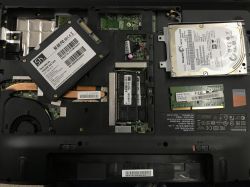
    After completing the compilation, go to the "mega328_st7565" directory in the project directory, there is the TransistorTester.hex file (flash memory content) and TransistorTester.eep (eeprom content). Place both files in the memory of the ATMEGA328P microcontroller using the selected ISP programmer. I used AVRISP MKII and software from AtmelStudio environment. To connect to the ISP connector in the tester, I used the connecting cables for the contact plate. The photo below shows the pinout of the connector.
    Change of the firmware of the LCR T4 M328 element tester from the elektroda.pl g Change of the firmware of the LCR T4 M328 element tester from the elektroda.pl g

    For the time of programming, we lock the button that turns on the device (e.g. with a clothes peg) to ensure continuous power supply of the microcontroller.

    If everything goes well, the tester will greet us with messages in Polish:
    Change of the firmware of the LCR T4 M328 element tester from the elektroda.pl g Change of the firmware of the LCR T4 M328 element tester from the elektroda.pl g


    We put our own logo.

    Perhaps logo placement is not some super ambitious and necessary task, but it is a good way to start playing with tester code. We have an area of 128x32 black and white pixels at our disposal (during the ongoing test). We'll write each pixel as a bit in a byte, and that takes 512B in a 512-element array. Each byte will be a vertical 8-pixel dash starting at the top of the x-coordinate of the LSB bit of the array element. After reading as many elements as the image width is (in our example 128), we read the next bar at the y-greek coordinate by 8 pixels.

    If we care about the logo and limit the memory consumption, we can think about a simple "compression", for example saving the coefficient of start and end lines horizontally or vertically instead of data for all pixels, for some pictures it will save memory.

    The black and white elektroda.pl logo from the home page is saved to a PNG file with a resolution of 128x32:
    Change of the firmware of the LCR T4 M328 element tester from the elektroda.pl g
    With a simple python code, we convert a PNG file into an array, in which each bit corresponds to a lit or unlit pixel on the LCD. We set the height and width of the PNG file so that they are equal to the power of 2. For a 128x32 image we will have 128x (32/8) = 512 element array, a single element of the array will be a byte. To write the codes, we use the knowledge gained about python and png here:
    Will the Sun clear the EPROM?
    Quickly written python 3 code will turn the PNG file into an array of bytes:

    [syntax=python]from PIL import Image
    i = Image.open("logo.png")

    xx=i.width
    yy=i.height

    print("szerokosc: "+str(xx)+" wysokosc: "+str(yy))

    if xx>128:
    print("Szerokosc wieksza od 128, to nie zadziala...");
    exit();

    if yy>32:
    print("Wysokosc wieksza od 32, to nie zadziala...");
    exit();

    if xx%2!=0 or yy%2!=0:
    print("Szerokosc lub wysokosc nie jest potega 2, to moze nie zadzialac...");


    data=i.load()

    print("const unsigned char PROGMEM logo["+str(int(xx*(yy/8)))+"]= {") #rozpoczynamy tablice

    for y in range(0,yy,8): #idziemy po wsp y obrazka
    for x in range(0,xx): #idziemy po wsp x obrazka
    b=0 #zerujemy wartosc bajt (wszystkie pixesle zgaszone)
    for n in range(0,8): #sprawdzamy kolejne pionowe 8 pixeli na danej wsp. x
    if y+n
    Attachments:
    • firmware_M328_elektroda.pl.zip (33.4 KB) You must be logged in to download this attachment.
    • logo.txt (3.1 KB) You must be logged in to download this attachment.
    • konwerter_logo.zip (836 Bytes) You must be logged in to download this attachment.

    Cool? Ranking DIY
    About Author
    TechEkspert
    Editor
    Offline 
    TechEkspert wrote 6959 posts with rating 5415, helped 16 times. Been with us since 2014 year.
  • ADVERTISEMENT
  • #2 16667071
    @GUTEK@
    Level 31  
    I also got the impression that this software is worse at measuring transistors, thyristors, etc. But I would have to have a second tester with the original software to check it.

    As for the modifications, here's mine:
    Change of the firmware of the LCR T4 M328 element tester from the elektroda.pl g

    - Z73 housing used
    - powered by a 18650 battery
    - TP4056 charger with a micro usb socket
    - MT3608 step-up converter set to 8V
  • #3 16667303
    piterek-23
    Level 33  
    Thanks for the description. In my free time I will test :)

    The "elektroda.pl" logo looks great and this is what the tester should look like from the very beginning, and the casing with the "elektroda.pl" engraving is already a fairy tale :)
  • #4 16667370
    Anonymous
    Anonymous  
  • #5 16669013
    szymon122
    Level 38  
    Is it possible to copy the original program to the computer before changing the software? Something like a backup.
  • #6 16669089
    Anonymous
    Anonymous  
  • #7 16669095
    szymon122
    Level 38  
    Christophorus wrote:
    If the microcontroller is protected against reading the program written in it, then there is no such possibility.

    I knew that much before writing the post ...

    I ask the author of the thread how it is in this case.
  • ADVERTISEMENT
  • #8 16669156
    Anonymous
    Anonymous  
  • #9 16669307
    Karaczan
    Level 42  
    My T4 was not secured. If I manage to find my load.

    As for the "originality" of the firmware ..
    It is from https://www.mikrocontroller.net/svnbrowser/transistortester/ that is original ;)
    This is the author's website of the original project, the Chinese simply copied it and flipped it on a massive scale. So I suspect that the factory fw is largely based on these sources.

    As for the measurements after changing fw, did you calibrate the tester after changing the software?
  • #10 16670062
    TechEkspert
    Editor
    @GUTEK@ wrote:
    I also got the impression that this software is worse at measuring transistors, thyristors, etc. But I would have to have a second tester with the original software to check it.


    Maybe you could get one of the gadgets https://www.elektroda.pl/rtvforum/shop.php and compare?

    szymon122 wrote:
    Christophorus wrote:
    If the microcontroller is protected against reading the program written in it, then there is no such possibility.

    I knew that much before writing the post ...
    I ask the author of the thread how it is in this case.


    I also suspect that it is secured, I must admit that I forgot to check and make a copy, and maybe the security issue depends on the copy?

    Karaczan wrote:

    As for the measurements after changing fw, did you calibrate the tester after changing the software?


    Yes, after placing a new fw, you need to perform a calibration, replacing fw is associated with uploading the hex file to flash and epp to eeprom, i.e. we start from scratch.
  • #11 16670126
    @GUTEK@
    Level 31  
    One that I have too few points to order - these points counted from 2015, probably two, it's a pity to take someone else since I already have such a tester.

    Someone has downloaded the original soft and is available in the topic about the modifications of these testers: https://www.elektroda.pl/rtvforum/topic3200555-60.html#15820165
    I used to check it if it works and it seems to be version 2.07, I don't know with any of these current testers.
  • #12 16675880
    logos2000
    Level 21  
    Included the factory firmware for M328 from the electrode store (2nd batch of blue button)
    Attachments:
    • M328 firmware.zip (39.16 KB) You must be logged in to download this attachment.
  • #13 16676822
    logos2000
    Level 21  
    And since the topic about changing the firmware is due to the fact that my original display did not survive the assembly, I decided to adapt a 2x16 display to the existing board (popular HD 47780)

    Connection diagram:

    Change of the firmware of the LCR T4 M328 element tester from the elektroda.pl g

    Ports D0 to D3 are brought to the front, while D4 and D5 must be pulled straight from the CPU.

    Change of the firmware of the LCR T4 M328 element tester from the elektroda.pl g Change of the firmware of the LCR T4 M328 element tester from the elektroda.pl g


    Effect of operation (later the LCD will be an element independent of the test plate, the assembly below was for trial)

    Change of the firmware of the LCR T4 M328 element tester from the elektroda.pl g

    in the firmware attachment
    Attachments:
    • mega328_2X16_menu.zip (60.2 KB) You must be logged in to download this attachment.
  • ADVERTISEMENT
  • #14 16676829
    TechEkspert
    Editor
    An interesting way to deal with a display crash, what's the symbol after the number in the second line of the display?
    I did not expect that there is a description of the ISP connector on the other side.
  • #16 16676912
    logos2000
    Level 21  
    TechEkspert wrote:
    An interesting way to deal with a display crash, what's the symbol after the number in the second line of the display?
    I did not expect that there is a description of the ISP connector on the other side.


    Honestly, I have no idea what [RL] means, when connecting 1-2, it does not display this message

    @GUTEK@ wrote:
    As if someone was looking for the original display: https://www.gearbest.com/lcd-led-display-module/pp_530259.html

    Since these displays are such a lame, I preferred to make it more solid :)
  • #17 16676919
    TechEkspert
    Editor
    @ logos2000 I mean this symbol after the number 2162.
  • #18 16676954
    logos2000
    Level 21  
    TechEkspert wrote:
    @ logos2000 I mean this symbol after the number 2162.


    Looking after a few resistors is a sign of ohms, but the fact that the ladder is strange, the firmware language is English.

    Edit.
    It turns out that this ladder was caused by the display, but at the target it displays beautifully :)

    I searched and searched for why the tester did not want to start after removing the old LCD, it turned out that the backlight is a control component of the transistor 9015 (M6), so the scalped diode is lit under the board.

    The power supply of the display and its backlight is taken directly from the factory LM7805, the current consumption is 40mA, so there is still a spare for the transistor.

    Change of the firmware of the LCR T4 M328 element tester from the elektroda.pl g Change of the firmware of the LCR T4 M328 element tester from the elektroda.pl g Change of the firmware of the LCR T4 M328 element tester from the elektroda.pl g
  • #20 16739192
    logos2000
    Level 21  
    gulson wrote:
    Here they boast with the software version V2.68:
    https://www.aliexpress.com/item/2016-V2-68-ES...apacitance-ESR-Meter-MOS-PNP/32714478296.html
    I do not know if it's true.


    True, apparently it is more accurate (it's hard to confirm it after one test), although the Registered badge on the project copied from the net is funny ...

    http://blog.goo.ne.jp/meg_8086/e/c42795fa1a6bbbd31f8c5102a806b70d

    And here is the firmware for various clones:
    https://yadi.sk/d/yW8xa5NJgUo5z
  • ADVERTISEMENT
  • #24 16745466
    gulson
    System Administrator
    Thanks, I know, that one is great, but so far my budget doesn't allow me.
  • #25 17451340
    nici
    VIP Meritorious for electroda.pl
    @TechEkspert Thank you very much for the first post. If I feel that I can, I will change Fw.
  • #26 17683886
    Norbert_lubin
    Level 17  
    Hey everyone ... colleagues, reading the description, I apparently did not understand everything and I fired the tester, the tester is in its current state such that after pressing the blue button it says "MTester Testing Vbat = 8.08v" and then it goes to "No unkown or damaged part. " and a question mark then nothing happens ....
    I wanted to do the programming with the TLL866A programmer on the ICSP connector but something went wrong because since the last fight, the minipro program cannot read the ID, I have "00 00 00" and nothing else.
    Due to the fact that everyone described the reprogramming method beautifully, there was an opportunity to make a guide for repairing the Tester :-) I know, I am not laughing hiii, but seriously, if colleagues have an idea, please play begging on your knees for help ... And as for the tester charge, I am interested in the one that has the largest amount of data on the study of mosfet transistors

    Hello, after connecting to pin 1,2, 3 jumpers for 3 pins, nothing happens is the same as I described earlier
    I will add that it is a tester with a blue button if it means the version and there is an Atmega 328P processor
  • #27 17684045
    TechEkspert
    Editor
    No unkown or damaged part, it appears regardless of whether there is something connected to pins 1,2,3 or not?
    What happens when the test pins 1,2,3 are shorted and the tester is started?

    ID "00 00 00" indicates a problem with communication with the microcontroller, maybe a problem with fusebits?

    Perhaps the microcontroller is damaged, then the solution would be to solder a new microcontroller, program it with the appropriate batch, and set the fusebits to use the quartz resonator.

    What are your ideas about the cause of such damage?
  • #28 17697217
    Norbert_lubin
    Level 17  
    The problem is solved, I changed the processor and a colleague jackfinch helped to reprogram for which thanks a lot for your interest.
  • #29 17697432
    TechEkspert
    Editor
    Which firmware was successfully uploaded, how do you rate the functionality?
  • #30 17705987
    Norbert_lubin
    Level 17  
    Hello, the version I uploaded is 1.13 from the Electrode and I will say that the measurement of mosfet transistors is amazing, I give much more information about the transistor than the original one. Thank you very much to the people who modified the tester feed, it's a great job, colleagues. Thank you
📢 Listen (AI):

Topic summary

✨ The discussion revolves around modifying the firmware of the LCR T4 M328 element tester, with users sharing experiences and technical insights on the process. Key points include the availability of source code for the tester, the necessity of calibration after firmware changes, and the challenges faced when attempting to back up original firmware. Users discuss various modifications, including housing changes, power supply adjustments, and display replacements. The conversation also touches on the compatibility of different microcontrollers, the importance of proper programming techniques, and the potential for improved measurement accuracy with updated firmware versions. Several users report successful firmware updates and calibration processes, while others seek assistance with issues related to programming and display functionality.
Generated by the language model.

FAQ

TL;DR: 100 % of T4 testers in one AliExpress listing ship with firmware “V2.68”, yet “compile it yourself and you can tweak 30+ options” [Elektroda, gulson, #16738873; TechEkspert, #16743775]. Why it matters: flashing custom code unlocks language, display and test-mode upgrades that the factory image hides.

Quick Facts

• MCU: ATmega328P, 32 kB flash + 1 kB EEPROM [Atmel Datasheet]. • Safe supply range: 6–12 V DC or 3.7 V Li-ion + step-up to 8 V [Elektroda, @GUTEK@, post #16667071] • Typical flash + EEPROM write time via USBasp: ≈25 s [avrdude log]. • Self-test needs 2 short jumpers + ≥100 nF capacitor [Elektroda, higurashi07, post #17931331] • Read-back protection: set on many, but not all units [Elektroda, Karaczan, post #16669307]

1. Can I back up the original firmware before flashing new code?

Only if the lock bits are clear. Many units have read-back protection, blocking any dump attempt [Elektroda, Anonymous, post #16669089] Some users reported unprotected chips, so test with avrdude; if the device ID returns “0x1E 0x95 0x0F” and memory reads without 0xFF only, you are lucky.

3. How do I compile the open-source firmware in Atmel Studio?

Follow this 3-step workflow:
  1. Create a new GCC project for ATmega328P.
  2. Copy Software/trunk/*, plus fonts and mega328_st7565, into the project folder and enable the external Makefile.
  3. Edit the Makefile flags, then press Build → Build Solution [Elektroda, TechEkspert, post #16666668]

4. What Makefile flags fix an upside-down or mirrored display?

Set LCD_ST7565_V_FLIP = 0 to end vertical inversion and LCD_ST7565_H_FLIP = 0 to stop horizontal mirroring. If the image is shifted, adjust LCD_ST7565_H_OFFSET from 4 to 0 [Elektroda, TechEkspert, post #16666668]

5. How do I calibrate the tester after flashing?

Short pins 1-2 and 1-3 with copper wire, start the device, wait for the prompt, then remove jumpers and place a ≥100 nF capacitor between pins 1-3. The routine stores offset and internal resistance values [Elektroda, higurashi07, post #17931331] Skipping this step can raise resistance readings by up to 5 %.

6. My screen shows random ASCII characters—what is wrong?

You loaded firmware for a different LCD controller. Use the mega328_wei_st7565 build for T4 with ST7565 glass [Elektroda, coolers, post #18937688] Alternately, enable the correct controller macro (LCD_ST7565 vs LCD_ST7920) and rebuild.

7. Does ATmega328PB work as a drop-in replacement?

No. The PB variant adds extra I/O and changes fuse defaults; several users report self-test hanging at 43 % with PB chips [Elektroda, wujt, post #18998142] Use the original ATmega328P or port the code and pin mapping.

8. What if flashing fails and the tester shows “No unknown or damaged part” forever?

The MCU may have corrupted fuses or flash. Check that CKSEL bits point to the 8 MHz crystal and that LOW FUSE = 0xF7, HIGH FUSE = 0xD9, EXT FUSE = 0xFC [Elektroda, TechEkspert, post #17684045] Re-flash HEX and EEP, then recalibrate.

10. How can I add my own 128×32 logo?

Convert a monochrome PNG to a 512-byte C array. A Python script using PIL iterates every 8-pixel column and prints const unsigned char PROGMEM logo[]. Replace the logo array in menu.c, re-compile and flash [Elektroda, TechEkspert, post #16666668]

11. Why doesn’t Zener diode mode work on my board?

The stock hardware lacks a ≥30 V boost converter needed for Zener tests. You must add a step-up (e.g., MT3608 set to 30 V) and enable WITH_VEXT in the Makefile [Elektroda, Anonymous, post #17938211]

12. Can I power the T4 from a single 18650 cell?

Yes. Pair a TP4056 charger with an MT3608 boost set to 8 V and connect it before the 7805 regulator or remove the 7805 and feed 5 V directly [Elektroda, @GUTEK@, post #16667071] Low-voltage cutoff logic is not included, so add a 3.3 V protector to avoid deep-discharge.

13. What causes mirrored display despite correct flags?

Solder bridges or flux between LCD flex contacts can invert bits. Cleaning the board with IPA fixed random image flips for one user [Elektroda, dragolice16, post #19793707]

14. Is it worth chasing pre-compiled HEX files?

If sources are public, building locally lets you localise menus, enable UJT or ESR extras, and avoid malware. “It doesn’t make sense to hunt hexes” when SVN is open [Elektroda, TechEkspert, post #16743775]

15. Edge case: what if the MCU ID reads 0x00 0x00 0x00?

Either wiring is wrong or fuse bits disabled SPI. Check the ISP header continuity, tie the On/Off button down for stable power, and confirm the reset line is low during programming [Elektroda, TechEkspert, post #17684045]

16. Where is the current code repository?

The original SVN migrated to GitHub: github.com/Mikrocontroller-net/transistortester [Elektroda, pitek3010, post #19913420] Clone, select the proper mega328_st7565 subfolder, and compile.
Generated by the language model.
ADVERTISEMENT